
Near-field exposure method

a near-field and exposure method technology, applied in the field of exposure methods, can solve the problems of decreasing proportional constants, difficult to improve resolution, and difficult for a projection exposure apparatus to form a pattern not greater than 0.10 m

Inactive Publication Date: 2006-12-05
CANON KK
View PDF14 Cites 9 Cited by
  • Summary
  • Abstract
  • Description
  • Claims
  • Application Information

AI Technical Summary

Benefits of technology

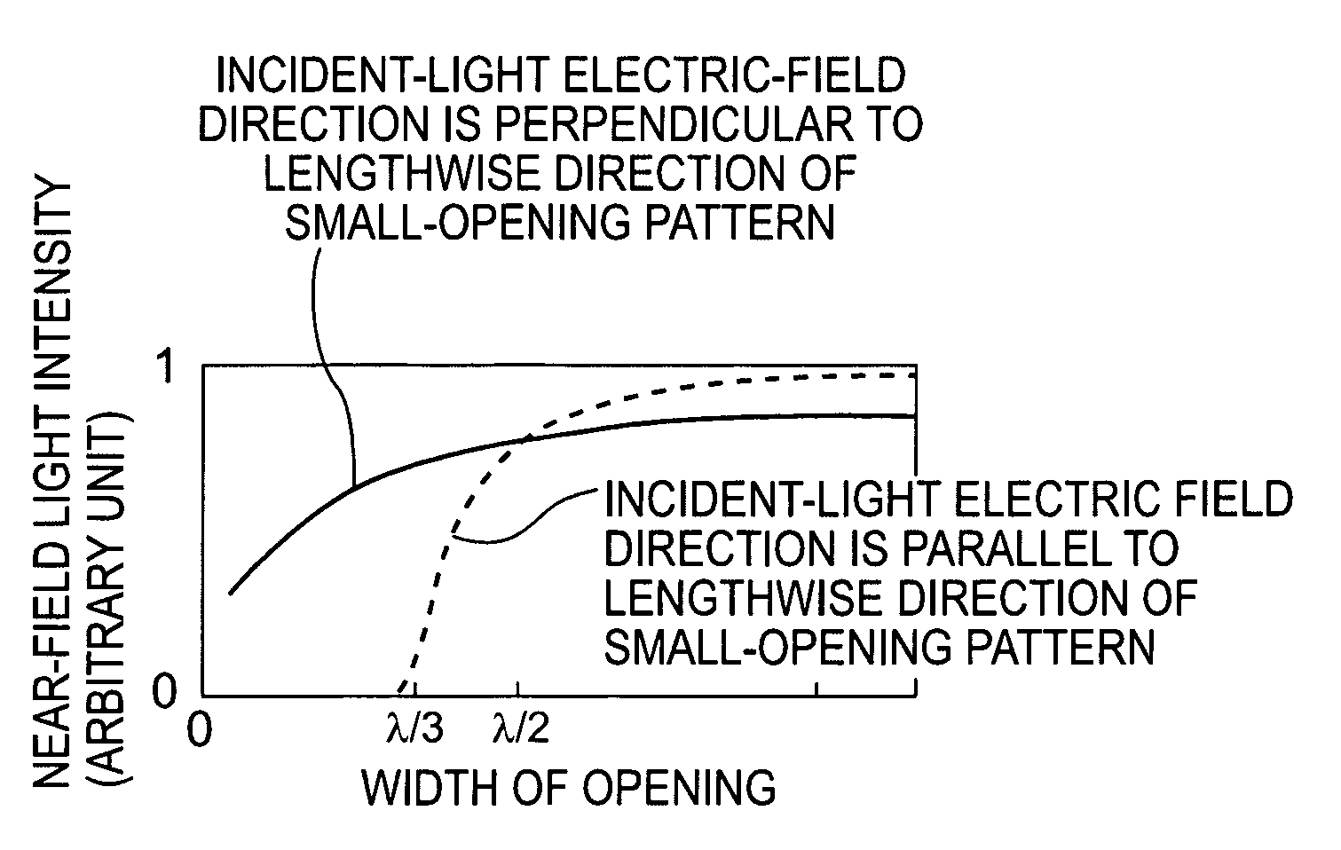
The present invention provides an exposure method for creating patterns on a workpiece using near-field light escaping from an opening of a mask. The improvement lies in the use of a mask with a light blocking film and a plurality of rectangular openings, with the openings having a width in a widthwise direction not greater than one-third of the exposure light and having its lengthwise directions extending in two or more directions along the mask surface. The non-polarized exposure light from a light source is projected onto the mask, and the near-field light escaping from the openings is used to perform exposure of a pattern on the workpiece. The widths of the openings are smaller than a cross-point between a first curve on a coordinate of a width of the openings and a second curve on the same coordinate for an incident-light electric-field direction perpendicular to the lengthwise direction of a small opening pattern and an incident-light electric-field direction parallel to the lengthwise direction of the small-opening pattern. This method allows for precise and accurate pattern creation on the workpiece.

Problems solved by technology

Therefore, it is difficult to improve the resolution by decreasing the proportional constants.
Even when an excimer laser is used, it is difficult for a projection exposure apparatus to form a pattern not greater than 0.10 μm.
Additionally, if there is any light source having a shorter wavelength present, optical materials to be used for the projection optical system (i.e., the lens glass material) could not transmit exposure light of such a short wavelength, and thus (because of the resultant failure of projection upon an object to be exposed), the exposure would end in failure.
For these reasons, it is very difficult to develop a practical glass material having a sufficiently large transmissivity to exposure light having a wavelength not greater than 150 nm, corresponding to a fine pattern of 0.10 μm, or narrower.
These factors also make the development of a practical glass material difficult.
This results in increased cost of mask production.

Method used


Image

  • Near-field exposure method
  • Near-field exposure method
  • Near-field exposure method

Examples


Embodiment Construction

[0028]Preferred embodiments of the present invention will now be described with reference to the attached drawings.

[0029]An exposure method, an exposure mask and an exposure apparatus to be provided in accordance with the present invention are such as described above.

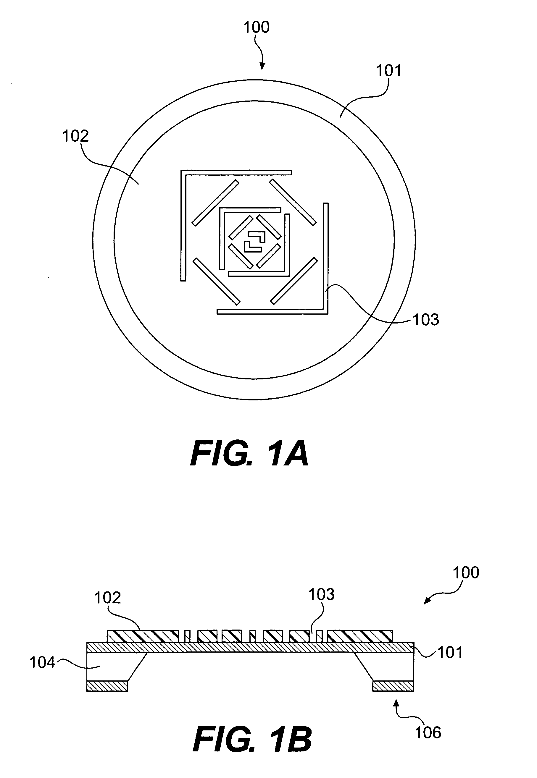
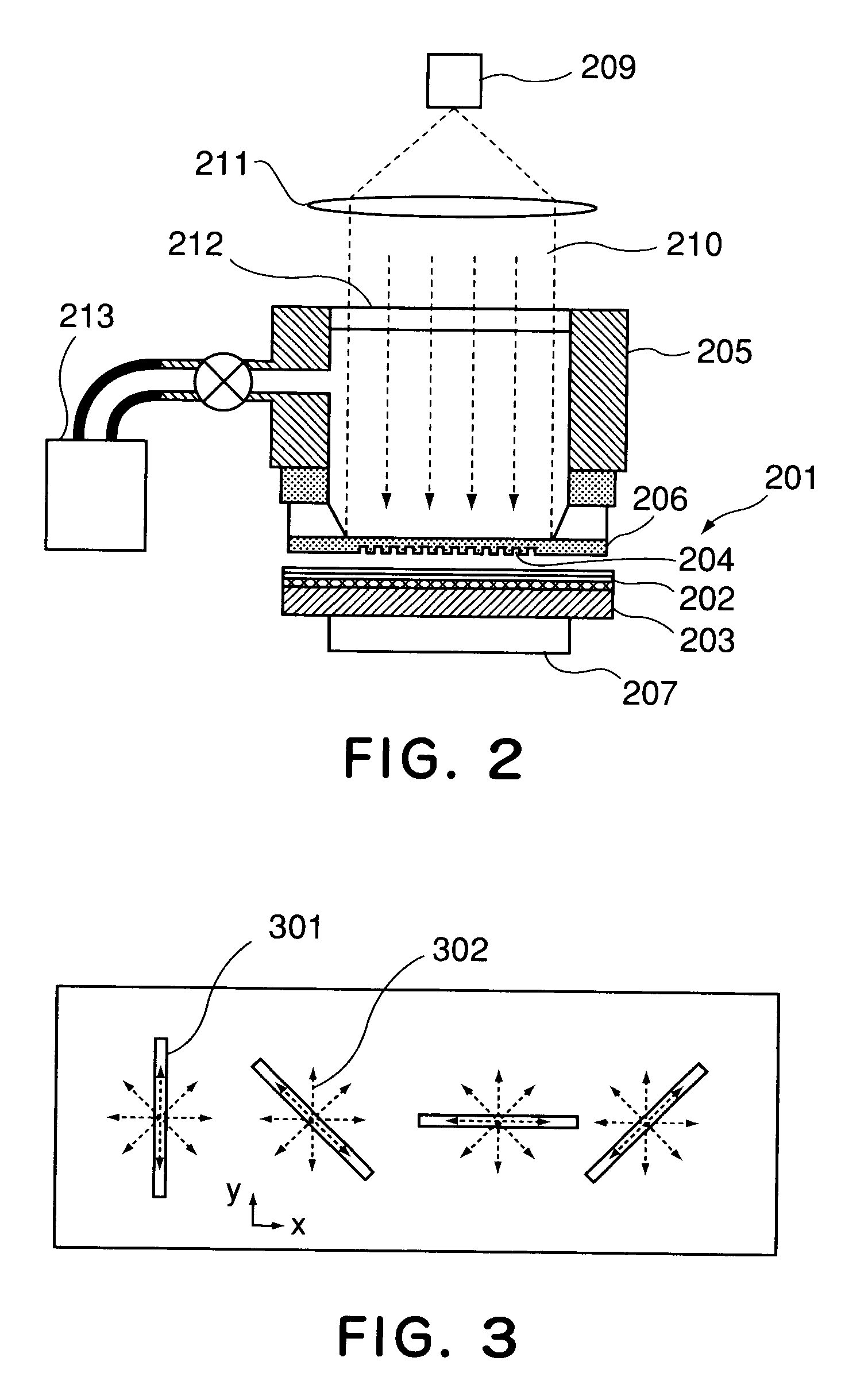
[0030]Referring now to the drawings, an exemplary exposure method 1 according to the present invention will be explained first. Here, embodied forms of the present invention will be described in detail with reference to FIGS. 1A, 1B and 2.

[0031]FIGS. 1A and 1B show the structure of an exposure mask according to the present invention. FIG. 2 is a view which illustrates an example of the structure of an exposure apparatus, using such an exposure mask.

[0032]Referring to FIGS. 1A and 1B, an exposure mask 100 according to the present invention will be explained. FIGS. 1A and 1B illustrate an exposure mask to be used in the exposure apparatus shown in FIG. 2. FIG. 1A illustrates the front surface side, and FIG. 1B is a sectio...


PUM

PropertyMeasurementUnit
wavelengthaaaaaaaaaa
wavelengthsaaaaaaaaaa

Abstract

A method for exposing a workpiece on the basis of near-field light escaping from an exposure mask having a light blocking film with a plurality of rectangular openings. The method includes protecting non-polarized near-field exposure light from a light source through the openings of the exposure mask to perform exposure of a pattern on the workpiece. The widths of the rectangular openings are smaller than that at a cross-point between a first curve on a coordinate of widths of the openings versus a near-field light intensity for an incident-light electric-field direction perpendicular to a lengthwise direction of a small-opening pattern and a second curve on the same coordinate for an incident-light electric-field direction parallel to the lengthwise direction of the small-opening pattern.

Description

FIELD OF THE INVENTION[0001]This invention relates to an exposure method, an exposure mask, and an exposure apparatus for use in the manufacture of semiconductor devices or optical devices.[0002]Reduction in size and thickness of electronic devices has been particularly desired in recent years, and this has made stricter the requirements for smallness of a semiconductor chip to be incorporated into such electronic devices. For example, as regards the design rule for a mask or reticle pattern, it is being reduced more and more, in order to accomplish mass-production of a 130 nm line-and-space (L & S) pattern. The line-and-space pattern is an image as projected upon a wafer, being in a state in which the line and the space have an even width, and thus, it is a scale that represents the resolution of exposure.[0003]Projection exposure apparatuses mainly used in recent years generally comprise an illumination optical system for illuminating a mask by use of a light flux emitted from a l...

Claims


Application Information

Patent Timeline
Patent Type & Authority Patents(United States)
IPC IPC(8): G03F7/20B82B3/00B82Y10/00B82Y40/00G03F1/14G03F1/50H01L21/027
CPCG03F1/14G03F7/2014G03F7/70325G03F7/7035G03F7/70566B82Y10/00G03F1/50G03F7/20G03F1/38
Inventor INAO, YASUHISAKURODA, RYOMIZUTANI, NATSUHIKO
Owner CANON KK
Learn More