
System and method for reducing nitrogen oxides in the exhaust of an internal combustion engine

a technology of nitrogen oxides and nitrogen oxides, which is applied in the direction of exhaust treatment, engine components, mechanical apparatus, etc., can solve the problems of comparatively low exhaust temperature, gasoline engines running on a lean mixture are faced with the same problems, and it is not possible to completely eliminate all gaseous, etc., to achieve a higher conversion rate, less hydrogen, and improved reaction selectivity

Inactive Publication Date: 2006-12-26
NUCELLSYS GMBH
View PDF28 Cites 5 Cited by
  • Summary
  • Abstract
  • Description
  • Claims
  • Application Information

AI Technical Summary

Benefits of technology

"The patent describes a heat exchanger design that uses active cooling to control the temperature of a DeNOx catalytic converter, which helps improve the selectivity of the reaction and reduce fuel consumption. A temperature sensor is also used for accurate control of the temperature. The multi-stage design of the converter provides better conversion of nitrogen oxides. Overall, the patent presents technical solutions for improving the performance of the DeNOx catalytic converter."

Problems solved by technology

Due to excess air that is almost always present in diesel engine exhaust, it is not possible to completely eliminate all gaseous pollutants—such as carbon monoxide, hydrocarbons, and nitrogen oxides (NOx)—using the 3-way catalytic converters that have been state of the art technology for gasoline engines for years.
Gasoline engines that run on a lean mixture are faced with the same problem.
An additional problem is the comparatively low exhaust temperature.
Future exhaust emission standards require conversion levels of nitrogen oxides in the exhaust of higher than 80%, which has been very difficult to achieve.
The conversion level of nitrogen oxides is not sufficient in a reduction process using only added fuel.
Similar problems are encountered when hydrogen is carried in pressure tanks or tanks for liquids.
Using the fuel intended for the internal combustion engine eliminates the need for an additional tank, which would require additional space and result in additional weight.

Method used


Image

  • System and method for reducing nitrogen oxides in the exhaust of an internal combustion engine
  • System and method for reducing nitrogen oxides in the exhaust of an internal combustion engine

Examples


Embodiment Construction

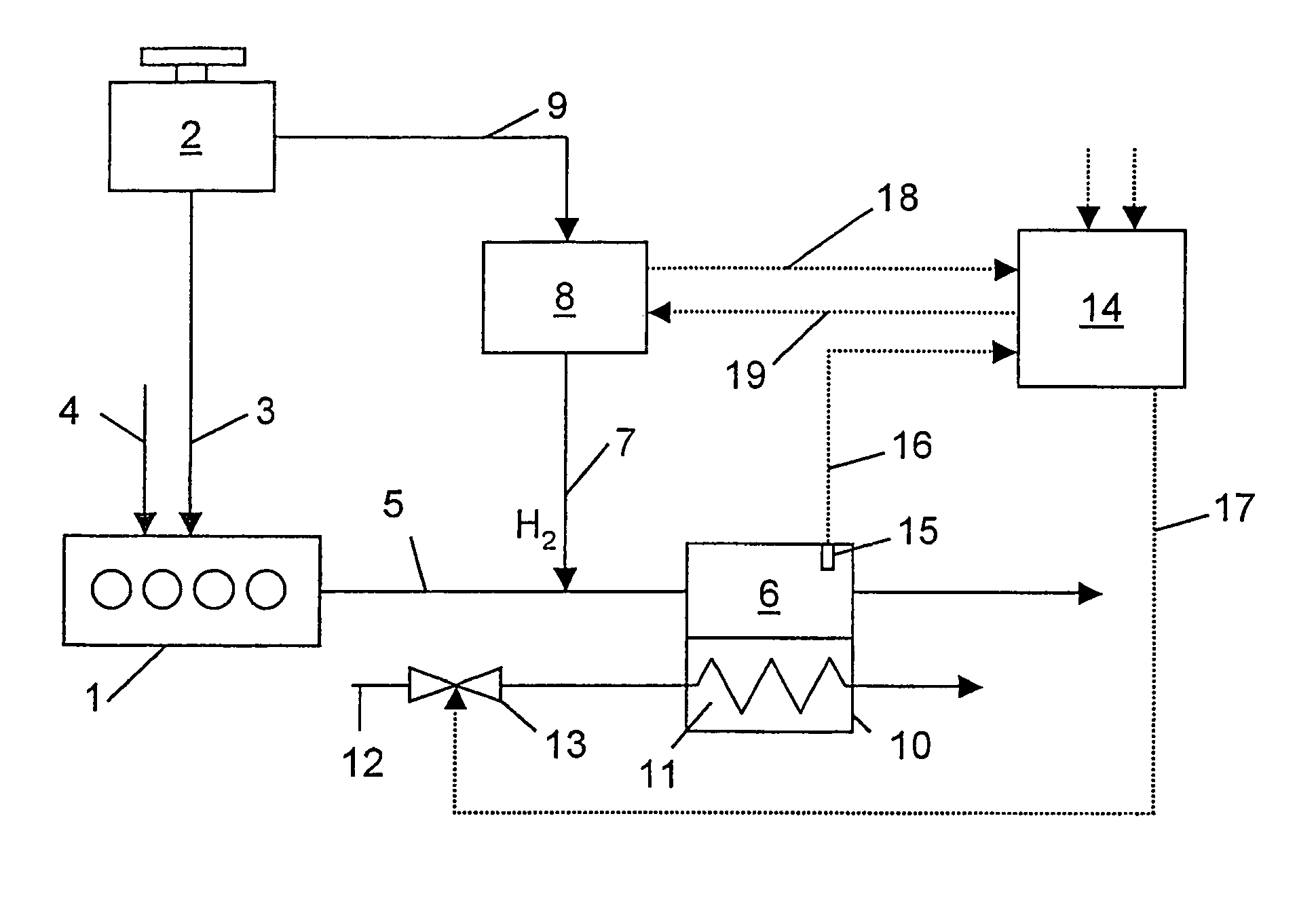
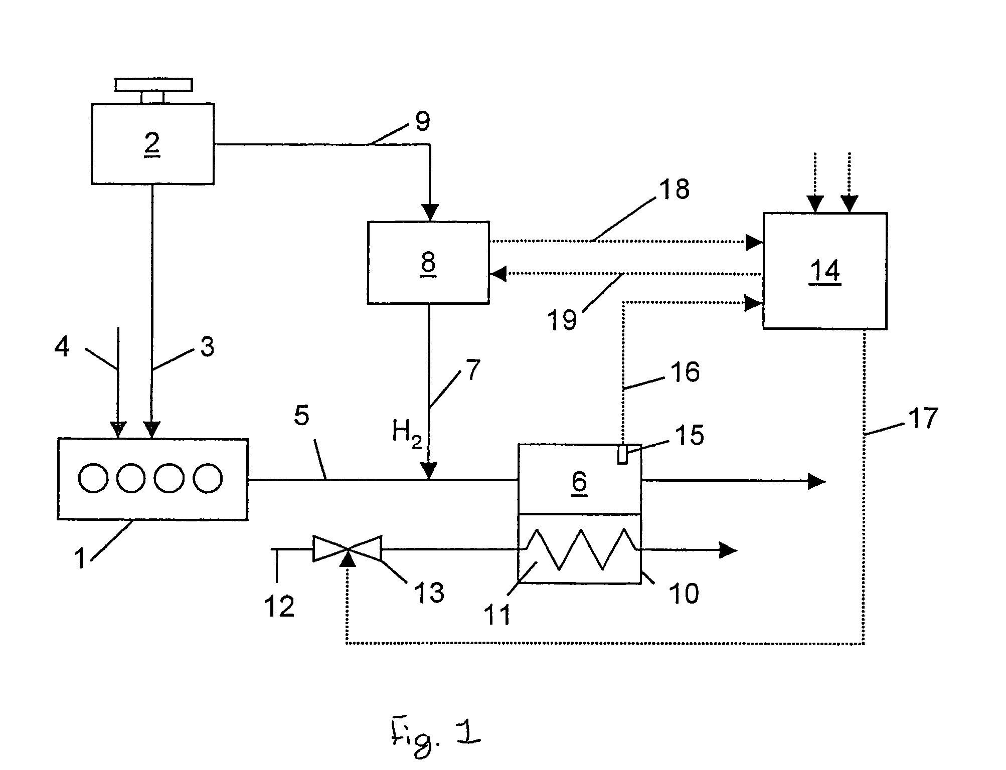
[0012]Referring to FIG. 1, an internal combustion engine 1 is supplied with fuel from a fuel tank 2 through a first fuel line 3 and with air through an intake line 4. In internal combustion engine 1, fuel is combusted together with the air, and the resulting exhaust is discharged through an exhaust line 5.

[0013]Exhaust line 5 contains a DeNOx catalytic converter 6, in which nitrogen oxides contained in the exhaust are converted by a reducing agent at a suitable catalyst. Hydrogen or a hydrogen-rich gas is used as the reducing agent, and is introduced into exhaust line 5 upstream of DeNOx catalytic converter 6 through a hydrogen feed line 7. In addition to DeNOx catalytic converter 6, exhaust line 5 may contain other components (not shown), such as, for example, additional oxidation catalysts or an exhaust sound absorber.

[0014]The hydrogen or hydrogen-rich gas is produced on-board the vehicle in a hydrogen-generating reactor 8 from the fuel used in internal combustion engine 1. Fuel ...


PUM


Abstract

In a system and method for the reduction of nitrogen oxides in the exhaust of an internal combustion engine, the exhaust line of the internal combustion engine contains a DeNOx catalytic converter, in which the nitrogen oxides are reduced by means of hydrogen that is produced on-board the vehicle. The DeNOx catalytic converter is incorporated into a temperature-controlled heat exchanger, allowing the DeNOx catalytic converter to be operated within a desired temperature range, thereby improving the level of conversion.

Description

FIELD OF THE INVENTION[0001]The invention concerns a system and a method to reduce nitrogen oxides in the exhaust of an internal combustion engine.DESCRIPTION OF THE RELATED ART[0002]Due to excess air that is almost always present in diesel engine exhaust, it is not possible to completely eliminate all gaseous pollutants—such as carbon monoxide, hydrocarbons, and nitrogen oxides (NOx)—using the 3-way catalytic converters that have been state of the art technology for gasoline engines for years. Even though diesel engine exhaust contains some reducing substances, such as carbon monoxide and hydrocarbons, their concentration is not significant compared to the amount of nitrogen oxides to be reduced. Gasoline engines that run on a lean mixture are faced with the same problem. An additional problem is the comparatively low exhaust temperature.[0003]Future exhaust emission standards require conversion levels of nitrogen oxides in the exhaust of higher than 80%, which has been very diffic...

Claims


Application Information

Patent Timeline
Patent Type & Authority Patents(United States)
IPC IPC(8): F01N3/00B01D53/94F01N3/02F01N3/04F01N3/05F01N3/20
CPCB01D53/9431B01D53/9495F01N3/0205F01N3/043F01N3/05F01N3/2046F01N3/206F01N2240/30F01N2610/04Y02T10/26Y02T10/12Y02A50/20
Inventor BENZ, UWEKEPPELER, BERTHOLDMARTIN, ANDRESCHUERSTEDT, PETERZUR MEGEDE, DETLEF
Owner NUCELLSYS GMBH
Learn More