
Perpendicular magnetic recording medium, manufacturing process of the same, and magnetic storage apparatus using the same

a magnetic recording medium and perpendicular magnetic technology, applied in the field of magnetic recording medium and magnetic storage apparatus, can solve the problems of spike noise caused by leakage magnetic flux caused by a domain wall in the soft magnetic underlayer, difficult to reach the real recording density of over 7.75 gbit per square centimeter, and thermal decay of magnetically recorded data, etc., to achieve high reliability and high reliability

Inactive Publication Date: 2006-12-26
WESTERN DIGITAL TECH INC +1
View PDF9 Cites 14 Cited by
  • Summary
  • Abstract
  • Description
  • Claims
  • Application Information

AI Technical Summary

Benefits of technology

[0010]The present invention is devised in consideration of the above-mentioned problems. Specifically, it is an object of the present invention to provide a perpendicular magnetic recording medium with a high medium S / N ratio and with a recording density of 7.75 or more Gbit per square centimeter, in which the quality of output signal is improved by controlling a magnetic domain in a soft magnetic underlayer and decay of recorded magnetization due to astray field is suppressed, and to easily realize a magnetic storage apparatus with a high recording density and with high reliability.
[0015]Consequently, the magnetic domain in the first amorphous soft magnetic layer and the second amorphous soft magnetic layer has a quasi-single domain, and the spike noise and the modulation in output signal are suppressed. Preferably, the thickness of the first amorphous soft magnetic layer is equal to that of the second amorphous soft magnetic layer, there by causing the feed-back of the magnetic flux between the first amorphous soft magnetic layer and the second amorphous soft magnetic layer, and a state of the quasi-single domain in the first amorphous soft magnetic layer and the second amorphous soft magnetic layer becomes stable.
[0016]Preferably, a material with the antiferromagnetism at the film formation is used as the antiferromagnetic layer. Specifically, the antiferromagnetic layer has a disordered alloy mainly composed of Fe and Mn or a disordered alloy mainly composed of Ir and Mn. An ordered alloy such as PtMn or NiMn is in a disordered state at the film formation and does not have the antiferromagnetism. The ordered alloy needs the ordering heat treatment in a magnetic field for some hours. Unpreferably, the treatment causes the medium manufacturing processing to be complicated and the manufacturing costs are increased.
[0028]As a protective layer of the perpendicular recording layer, a film having the thickness of 3 nm or more and 10 nm or less mainly composed of carbon is formed, and a lubricant layer such as perfluoroalkylpolyether is formed. Thus, the perpendicular recording medium is obtained with high reliability.
[0029]According to the present invention, there is provided a magnetic storage apparatus comprising: the perpendicular magnetic recording medium having a perpendicular recording layer on a substrate via a soft magnetic underlayer; a driving section which drive the perpendicular magnetic recording medium in a recording direction; a magnetic head having a recording section and a reproducing section; a unit which relatively moves the magnetic head to the perpendicular magnetic recording medium; and a recording / reproducing processing unit which inputs a signal from the magnetic head and reproduces an output signal from the magnetic head, wherein the recording section of the magnetic head comprises a single-pole-type head, and the reproducing section of the magnetic head comprises a high-sensitive element using a magnetoresistive effect or tunneling magnetoresistive effect. Thus, the magnetic storage apparatus is realized with the a real recording density of 7.75 Gbit per square centimeter and with high reliability.

Problems solved by technology

However, the increase of a real recording density clearly causes the thermal decay that magnetically recorded data is erased under the influence of circumferential heat.
In the conventional a real recording system, it is considered difficult to reach the a real recording density of over 7.75 Gbit per square centimeter.
However, since the double-layer perpendicular recording medium has the soft magnetic underlayer with a high saturation magnetic flux density (Bs), the leakage magnetic flux caused from a domain wall in the soft magnetic underlayer is observed as a spike noise.
The motion of the domain wall in the soft magnetic underlayer cause the decay of the recorded magnetization and, further, the stray field in the apparatus concentrates to the recording head, thereby causing the decay of the recorded magnetization just under the recording head.

Method used


Image

  • Perpendicular magnetic recording medium, manufacturing process of the same, and magnetic storage apparatus using the same
  • Perpendicular magnetic recording medium, manufacturing process of the same, and magnetic storage apparatus using the same
  • Perpendicular magnetic recording medium, manufacturing process of the same, and magnetic storage apparatus using the same

Examples


first embodiment

[0051](First Embodiment)

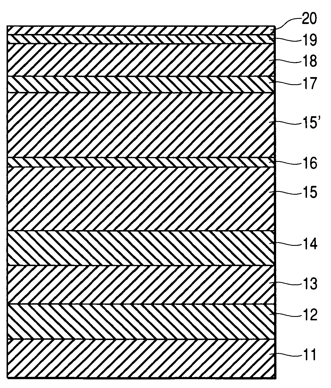
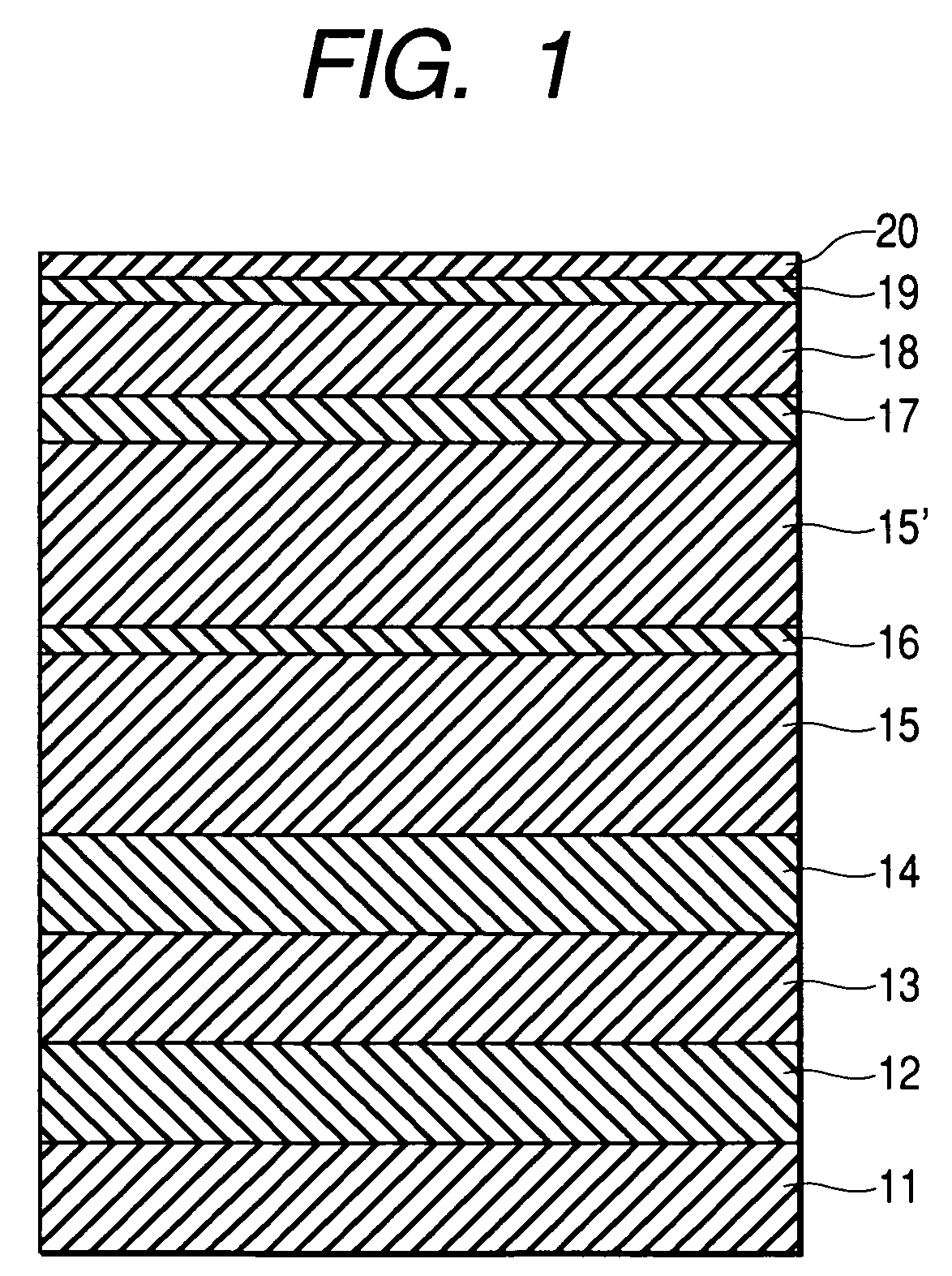
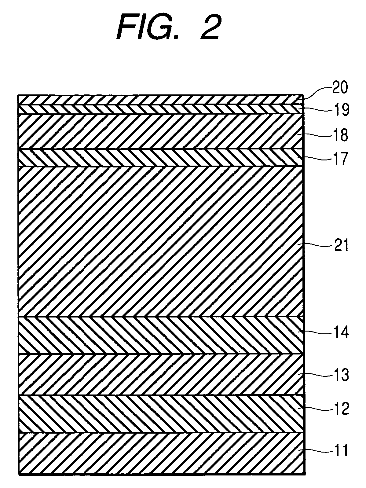
[0052]FIG. 1 shows the layer structure of a perpendicular magnetic recording medium according to the first embodiment. A 2.5-type glass disk is employed as a substrate 11. Sequentially formed on the substrate 11 are a pre-coating layer 12, an fcc-metal layer 13, an antiferromagnetic layer 14, and a first amorphous soft magnetic layer 15, by sputtering. Then, the substrate 11 is heated approximately to 200° C. by a lamp heater and is cooled to approximately 60° C. in a magnetic field. The magnetic field upon cooling is directed from the outer periphery to the inner periphery along the radial of the disk substrate. The magnetic field ranges from 8 kA / m to 10 kA / m on the disk substrate. Then, a non-magnetic layer 16, a second amorphous soft magnetic layer 15′, an intermediate layer 17, a perpendicular recording layer 18, and a protective layer 19 are sequentially formed on the substrate 11. Table 1 shows a target composition, an Ar gas pressure, and the thicknes...

second embodiment

[0065](Second Embodiment)

[0066]FIG. 8 shows the layer structure of a perpendicular magnetic recording medium according to the second embodiment of the present invention. A 2.5-type glass disk is employed as the substrate 11. Sequentially formed on the substrate 11 are the pre-coating layer 12, the fcc-metal layer 13, the antiferromagnetic layer 14, the first amorphous soft magnetic layer 15, a first ferromagnetic layer 81, the non-magnetic layer 16, a second ferromagnetic layer 81′, and a second amorphous soft magnetic layer 15′ by sputtering. Then, the substrate 11 is heated to approximately 250° C. by a lamp heater, the intermediate layer 17, and the perpendicular recording layer 18 are sequentially formed on the substrate 11, and the substrate 11 is then cooled approximately to 60° C. in a magnetic field. The substrate temperature just before entering a cooling unit with a magnetic field is approximately 200° C. The magnetic field upon cooling is directed from the outer periphery...

third embodiment

[0071](Third Embodiment)

[0072]FIG. 9 shows the layer structure of a perpendicular magnetic recording medium according to the third embodiment of the present invention. A 2.5-type glass disk is employed as the substrate 11. Sequentially formed on the substrate 11 are the pre-coating layer 12, the fcc-metal layer 13, the antiferromagnetic layer 14, and a first amorphous soft magnetic layer 91, by sputtering. Then, the substrate 11 is heated approximately to 200° C. by a lamp heater, and the substrate 11 is then cooled approximately to 60° C. in a magnetic field. The magnetic field upon cooling is directed from the outer periphery to the inner periphery along the radius of the disk substrate. The magnetic field ranges from 8 kA / m to 10 kA / m on the disk substrate.

[0073]After that, sequentially formed on the substrate 11 are the first non-magnetic layer 16, a second amorphous soft magnetic layer 92, a second non-magnetic layer 16′, a third amorphous soft magnetic layer 93, the intermedia...


PUM


Abstract

A soft magnetic underlayer includes a first amorphous soft magnetic layer to which an exchange bias magnetic field is applied directly from an antiferromagnetic layer or via a ferromagnetic layer, and a second amorphous soft magnetic layer which is formed on the first amorphous soft magnetic layer via a non-magnetic layer. The first amorphous soft magnetic layer and the second amorphous soft magnetic layer are antiferromagnetically coupled.

Description

BACKGROUND OF THE INVENTION[0001]1. Field of the Invention[0002]The present invention relates to a magnetic recording medium and a magnetic storage apparatus, more particularly, to a magnetic recording medium having an a real recording density of 7.75 Gbit per square centimeter and a magnetic storage apparatus including the magnetic recording medium.[0003]2. Discussion of the Background[0004]Since 1998, the a real recording density of a hard disk drive is increased at an annual rate of 100 percent. However, the increase of a real recording density clearly causes the thermal decay that magnetically recorded data is erased under the influence of circumferential heat. In the conventional a real recording system, it is considered difficult to reach the a real recording density of over 7.75 Gbit per square centimeter.[0005]Unlike the longitudinal recording system, the perpendicular recording system has the characteristic that the demagnetization field acting between adjacent bits is redu...

Claims


Application Information

Patent Timeline
IPC IPC(8): G11B5/66G11B5/70G11B5/667G11B5/127G11B5/73G11B5/738G11B5/84
CPCG11B5/1278G11B5/66G11B5/667G11B5/84G11B5/678
Inventor TANAHASHI, KIWAMUARAI, REIKOKIKUGAWA, ATSUSHI
Owner WESTERN DIGITAL TECH INC
Learn More