Rotary pump with hydrodynamically suspended impeller

a technology of hydrodynamic suspension and rotor, which is applied in the direction of prosthesis, liquid fuel engine, therapy, etc., can solve the problems of reducing the service life of the rotor of the motor providing the shaft torque, the rotor of the motor remaining to be supported, and the seal on the shaft may leak, etc., to achieve the effect of reducing the radius

Inactive Publication Date: 2007-01-02
TECH SYDNEY UNIV OF +2
View PDF91 Cites 49 Cited by
  • Summary
  • Abstract
  • Description
  • Claims
  • Application Information

AI Technical Summary

Benefits of technology

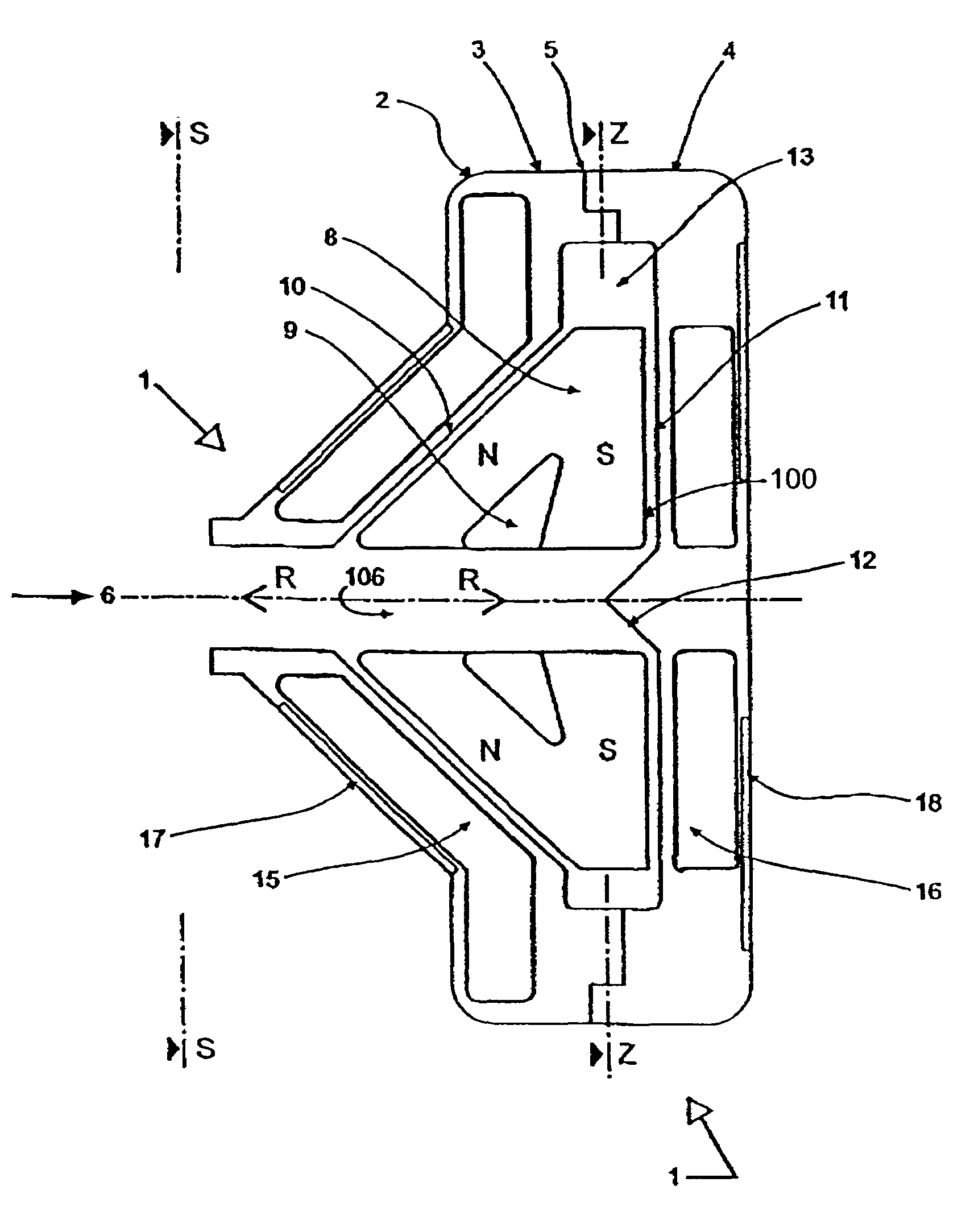
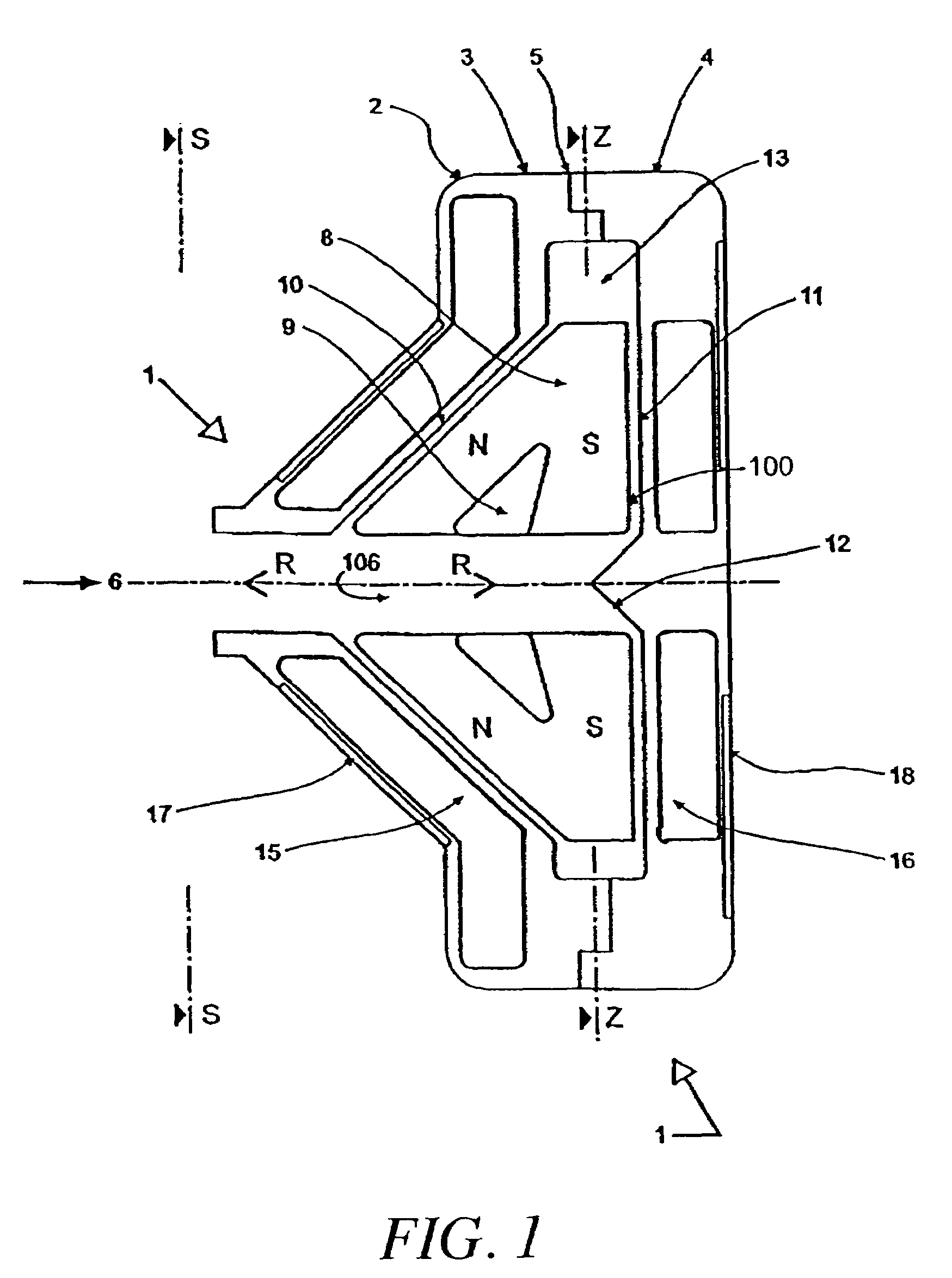
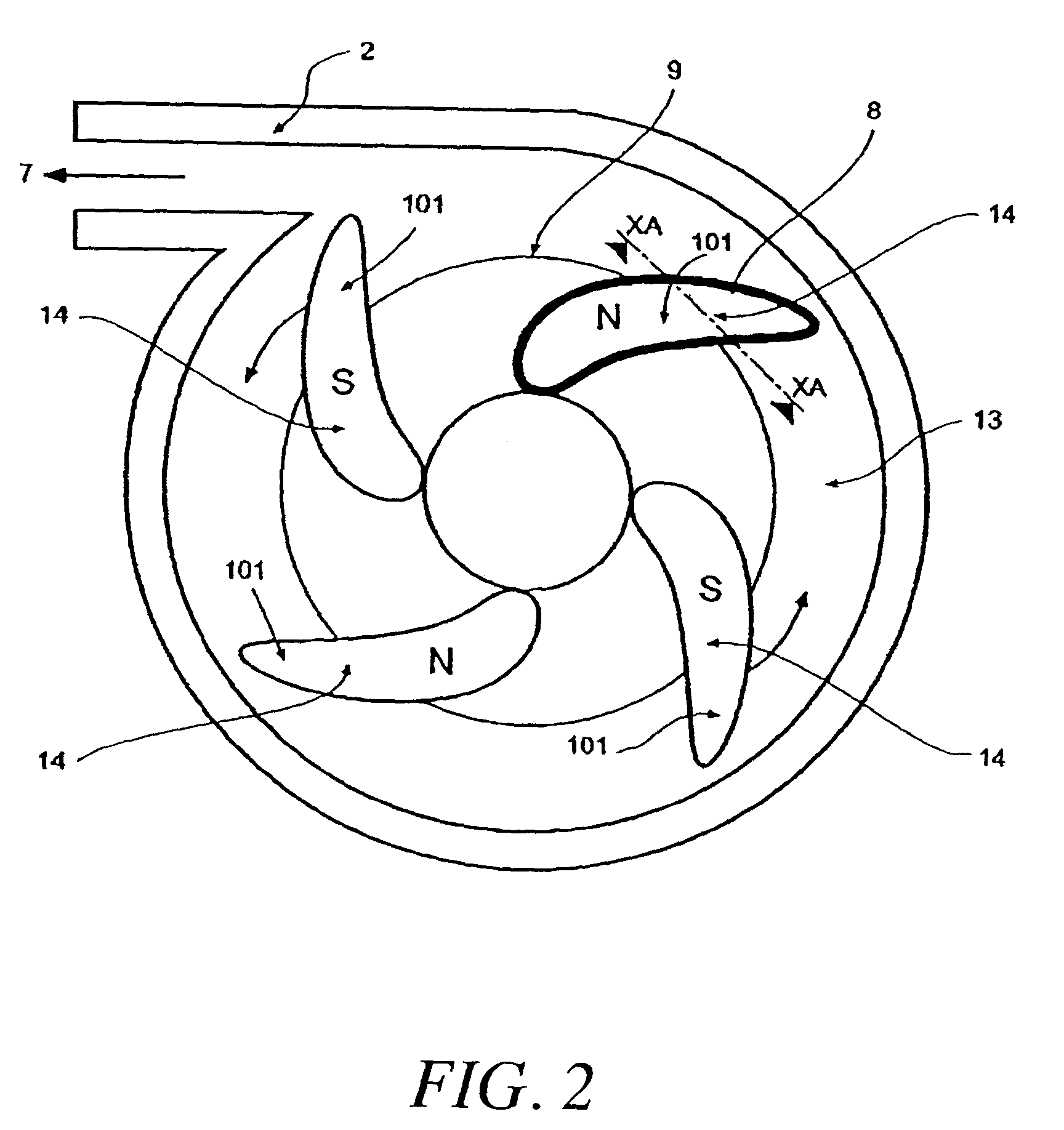
[0014]In preferred embodiments of the invention, the pump is of centrifugal or mixed flow type with impeller blades open on both the front and back faces of the housing. At least one face of the housing is made conical, in order that the thrust perpendicular to it has a radial component, which provides a radial restoring force to a radial displacement of the impeller axis. Similarly, an axial displacement toward either the front or the back face increases the thrust from that face and reduces the thrust from the other face. Thus the sum of the forces on the impeller due to inertia (within limits), gravity and any bulk radial or axial hydrodynamic force on the impeller can be countered by a restoring force from the thrust bearings after a small displacement of the impeller within the housing relative to the housing in either a radial or axial direction.
[0015]In the preferred embodiment, the impeller driving torque derives from the magnetic interaction between permanent magnets within the blades of the impeller and oscillating currents in windings encapsulated in the pump housing.

Problems solved by technology

Several of these characteristics are very difficult to meet in a conventional pump configuration including a seal, i.e. with an impeller mounted on a shaft which penetrates a wall of the pumping cavity, as exemplified by the blood pumps referred to in U.S. Pat. No. 3,957,389 to Rafferty et al., U.S. Pat. No. 4,625,712 to Wampler, and U.S. Pat. No. 5,275,580 to Yamazaki.
Two main disadvantages of such pumps are firstly that the seal needed on the shaft may leak, especially after wear, and secondly that the rotor of the motor providing the shaft torque remains to be supported, with mechanical bearings such as ball-bearings precluded due to wear.
Contact or pivot bearings, as exemplified by U.S. Pat. No. 5,527,159 to Bozeman et al. and U.S. Pat. No. 5,399,074 to Nos6 et al., have potential problems due to wear, and cause very high localised heating and shearing of the blood, which can cause deposition and denaturation of plasma proteins, with the risk of embolisation and bearing seizure.
Position measurement and feedback control introduce significant complexity, increasing the failure risk.
Power use by the control current implies reduced overall efficiency.
Furthermore, size, mass, component count and cost are all increased.
U.S. Pat. No. 5,507,629 to Jarvik claims to have found a configuration circumventing Earnshaw's Theorem and thus requiring only passive magnetic bearings, but this is doubtful and contact axial bearings are included in any case.
It would be inefficient to pass all the fluid through the bearing gap, of small cross-sectional area, as this would demand an excessive pressure drop across the bearing.

Method used


Image

  • Rotary pump with hydrodynamically suspended impeller
  • Rotary pump with hydrodynamically suspended impeller
  • Rotary pump with hydrodynamically suspended impeller

Examples


third embodiment

[0089]With reference to FIGS. 7 to 15 inclusive there is shown a further preferred embodiment of the pump assembly 200.

[0090]With particular reference initially to FIG. 7 the pump assembly 200 comprises a housing body 201 adapted for bolted connection to a housing cover 202 and so as to define a centrifugal pump cavity 203 therewithin.

[0091]The cavity 203 houses an impeller 204 adapted to receive magnets 205 within cavities 206 defined within blades 207. As for the first embodiment the blades 207 are supported from a support cone 208.

[0092]Exterior to the cavity 203 but forming part of the pump assembly 200 there is located a body winding 209 symmetrically mounted around inlet 210 and housed between the housing body 201 and a body yoke 211.

[0093]Also forming part of the pump assembly 200 and also mounted external to pump cavity 203 is cover winding 212 located within winding cavity 213 which, in turn, is located within housing cover 202 and closed by cover yoke 214.

[0094]The winding...


PUM

PropertyMeasurementUnit
distanceaaaaaaaaaa
distanceaaaaaaaaaa
diameteraaaaaaaaaa

Abstract

This invention relates to rotary pumps adapted, but not exclusively, for use as artificial hearts or ventricular assist devices and, in particular, discloses in preferred forms a seal-less shaft-less pump featuring open or closed (shrouded) impeller blades with the edges of the blades used as hydrodynamic thrust bearings and with electromagnetic torque provided by the interaction between magnets embedded in the blades and a rotating current pattern generated in coils fixed relative to the pump housing.

Description

RELATED APPLICATIONS[0001]This application is a continuation of prior application Ser. No. 09 / 734,532 filed Dec. 11, 2000, now U.S. Pat. No. 6,609,883 which is a continuation of prior application Ser. No. 09 / 281,608 filed Mar. 30, 1999 (now U.S. Pat. No. 6,227,797, issued May 8, 2001), which is a continuation of PCT / AU98 / 00725 filed Sep. 7, 1998, which claims priority to Australian Patent AU PO9027 filed Sep. 5, 1997.FIELD OF THE INVENTION[0002]This invention relates to rotary pumps adapted, but not exclusively, for use as artificial hearts or ventricular assist devices and, in particular, discloses in preferred forms a seal-less shaft-less pump featuring open or closed (shrouded) impeller blades with the edges of the blades used as hydrodynamic thrust bearings and with electromagnetic torque provided by the interaction between magnets embedded in the blades and a rotating current pattern generated in coils fixed relative to the pump housing.BACKGROUND ART[0003]This invention relate...

Claims


Application Information

Patent Timeline
Patent Type & Authority Patents(United States)
IPC IPC(8): A61N1/362A61M1/10F04D13/02A61M1/12F01D25/22F04C2/00F04D13/06F04D29/04F04D29/047F16C39/06
CPCA61M1/101F01D25/22F04D29/047F16C32/044F04D13/00F04D13/064A61M1/1017A61M1/1031A61M1/12F16C2316/18Y10T29/49336F16C2360/44Y10S415/90A61M60/824A61M60/422A61M60/148A61M60/237A61M60/178A61M60/508
Inventor WOODARD, JOHN CAMPBELLWATTERSON, PETER ANDREWTANSLEY, GEOFFREY DOUGLAS
Owner TECH SYDNEY UNIV OF
Why Eureka
Try Eureka