Method for making multi-layer ceramic acoustic transducer

a multi-layer ceramic and transducer technology, applied in piezoelectric/electrostrictive transducers, transducer types, generators/motors, etc., can solve the problems of reducing electrical efficiency, affecting the sensitivity of elements, and the inability to optimize parameters to match the electrical impedance of cables

Inactive Publication Date: 2007-01-02
GENERAL ELECTRIC CO
View PDF11 Cites 31 Cited by
  • Summary
  • Abstract
  • Description
  • Claims
  • Application Information

AI Technical Summary

Benefits of technology

[0010]The present invention is directed to simple methods for preparing a multi-layer acoustic transducer with reduced total electrical impedance. The methods are based on the stacking of individual piezoelectric layers with metallized surfaces to form a plate in which the metal layers are electrically connected to form interdigitated electrodes. The total electrical impedance of a multi-layer stack comprised of piezoelectric layers connected in this manner is inversely related to the square of the number of layers in the stack. This provides for better matching of the acoustic stack impedance to that of the electrical cable and improved acoustic element sensitivity.

Problems solved by technology

Since the acoustic response and frequency of a piezoelectric element are optimized for specific relationships relating to geometric area and thickness, these parameters cannot be optimized to match the electrical impedance of the cable.
This impedance mismatch greatly reduces electrical efficiency and, hence, element sensitivity.
However, for structures formed by this method, it is difficult to maintain the tolerances necessary for ultrasound transducers since co-firing of the piezoelectric and electrode materials can lead to waviness or non-planarity in the layers.
However, drilling of ceramics is a difficult feat, particularly so for small holes through thicker ceramic substrates.
Low-frequency acoustic transducers possess a ceramic that may be too thick to easily form vias and small element size for higher-frequency transducers requires a high density of vias, which weakens the ceramic structure.
This can be difficult to accomplish due to the aspect ratio of the hole unless the via is large in area.

Method used


Image

  • Method for making multi-layer ceramic acoustic transducer
  • Method for making multi-layer ceramic acoustic transducer
  • Method for making multi-layer ceramic acoustic transducer

Examples


Embodiment Construction

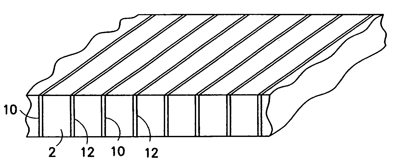
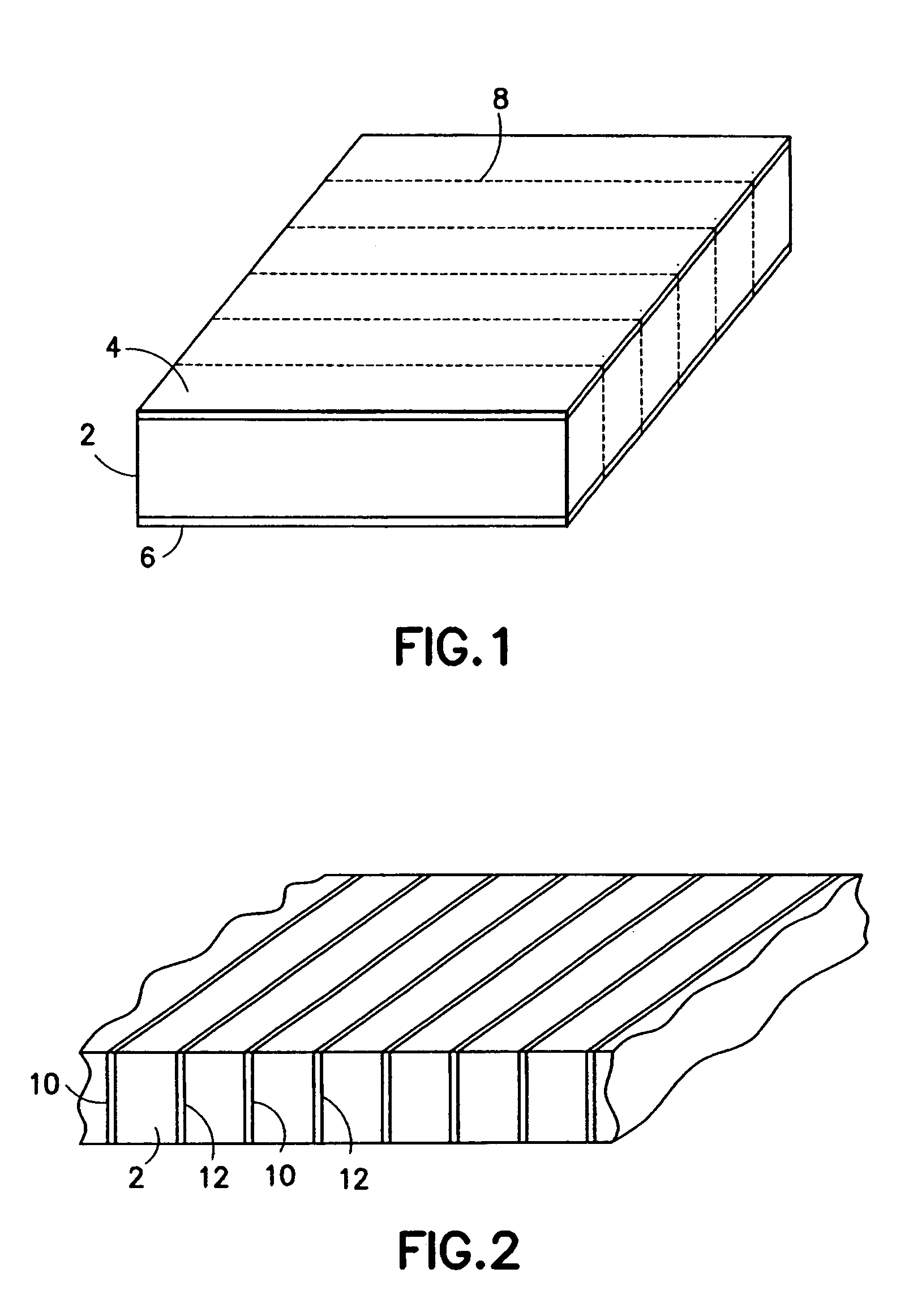
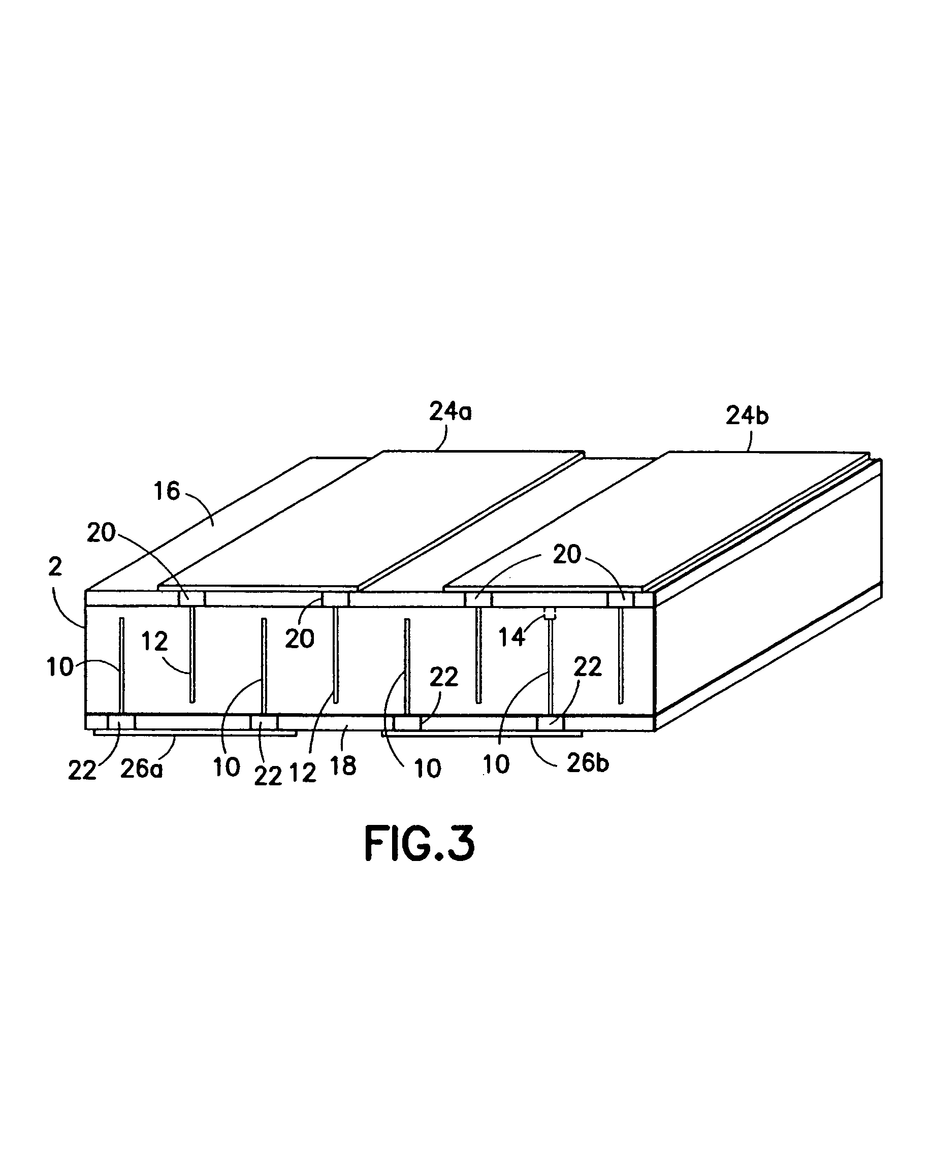
[0020]The method disclosed herein involves preparing a multi-layer acoustic stack based on laminating individual piezoelectric layers that possess metal electrodes on both faces, followed by connecting these electrodes in a manner that yields an interdigitated electrode connection. These methods are useful for preparing elements in both a linear acoustic array and also small elements for a two-dimensional acoustic array. Such acoustic arrays are useful for medical imaging applications.

[0021]The method disclosed herein for forming multi-layer piezoelectric acoustic transducers does not entail weakening the structural integrity of the piezoelectric element by removal of a portion of the ceramic element. Furthermore, the method is capable of preparing multi-layer stacks possessing several layers without added complexity. The method is based on laminating together discrete bars of metallized piezoelectric ceramic in such a manner as to form a laminated ceramic plate possessing internal ...


PUM

PropertyMeasurementUnit
electrical impedanceaaaaaaaaaa
impedanceaaaaaaaaaa

Abstract

Methods for preparing a multi-layer acoustic transducer with reduced total electrical impedance. The methods are based on the stacking of individual piezoelectric layers with metallized surfaces to form a plate in which the metal layers are electrically connected to form interdigitated electrodes. The total electrical impedance of a multi-layer stack comprised of piezoelectric layers connected in this manner is inversely related to the square of the number of layers in the stack. This provides for better matching of the acoustic stack impedance to that of the electrical cable and improved acoustic element sensitivity.

Description

BACKGROUND OF THE INVENTION[0001]This invention generally relates to multi-layer piezoelectric ceramic transducers. In particular, the invention relates to the design of ultrasound transducers to improve the sensitivity of an ultrasound imaging system.[0002]Acoustic transducers used in ultrasound imaging are constructed of a piezoelectric material whose surfaces are metal coated and connected to a potential (signal) and ground source respectively. This piezoelectric material is typically comprised of a composition of lead zirconate titanate (PZT) ceramic. During operation, a high-frequency electrical waveform is applied to the PZT electrodes, causing a change in ceramic dimension and generating an acoustic pressure wave or pulse. Conversely when an acoustic reflection contacts the surface of the piezoelectric material, it generates a voltage difference across the electrodes that is detected as a receive signal.[0003]Coaxial cables connecting the acoustic transducer to the system use...

Claims


Application Information

Patent Timeline
Patent Type & Authority Patents(United States)
IPC IPC(8): B32B37/00H01L41/08H04R17/00H01L41/083H01L41/22H01L41/27H04R31/00
CPCH01L41/277H01L41/083Y10T156/1062Y10T29/42H10N30/50H10N30/057
Inventor BAUMGARTNER, CHARLES E.LEWANDOWSKI, ROBERT S.
Owner GENERAL ELECTRIC CO
Why Eureka
Try Eureka