Ethernet connection of airborne radar over fiber optic cable

Active Publication Date: 2007-01-02
ROCKWELL COLLINS INC
19 Cites 45 Cited by

AI-Extracted Technical Summary

Problems solved by technology

First, electric power must be supplied to the antenna for its various movements, which require mechanical operation.
For one thing, in a conventional system, signals are conducted from the antenna to a receiver (at the processing array) through a waveguide, which typically incurs a 2–5 dB loss in transmission.
As more radar data are...

Method used

[0023]By using the fiber optic cable 125, cable-induced EMI and RFI is eliminated. As such, the weather radar system may even be optionally implemented with additional sensor systems, for example, a lightning detection sensor 207 as shown in FIG. 2. It should be noted that virtually any detection sensor systems that require the detection signals to be transmitted to the electronic bay 20 for further processing may take advantage of the fiber optic cabling in accordance with the present invention. In one embodiment, as illustrated in FIG. 2 (b), the detected signals from the sensors 207, 250 are transmitted to the fiber optic cable 260, 262, respectively, connected between the detection sensor systems and the electronic bay 20. In other embodiment, such as one illustrated in FIG. 2 (c), the detection signals may be multiplexed with the cabling 125, such that the interface between the electronic bay 20 and the cabling is simplified by the use of the MUX 270. While FIGS. 2 (a)–(c) ill...

Benefits of technology

[0008]An Ethernet connection of airborne radar systems over a fiber optic cable link is disclosed. The invention uses a fiber optic cable signal path to meet the increased radar throughput requirement. By digitizing the radar pulse pairs in high proximity to the antenna/receiver and replacing waveguide transmission of ana...

Abstract

A weather radar signal path for an aircraft. The signal path has an antenna, a digital down-converter, a first transceiver, fiber optic cabling, a second transceiver and a processing unit. The antenna is adapted to, in a first mode, receive reflected radar signals from atmosphere ahead. The digital down-converter is adapted to convert the reflected radar signals received by the antenna into digital radar signals at a lower frequency. The first transceiver is adapted to, in the first mode, at least transmit the digital radar signals through said fiber optic cabling. The fiber optic cabling is adapted to, in the first mode, transfer the digital radar signals between the first and second transceivers. The second transceiver is adapted to, in the first mode, receive said digital radar signals from the fiber optic cabling. The processing unit is adapted to, in the first mode, process the digital radar signals to generate weather information based on predetermined algorithm.

Application Domain

Technology Topic

Image

  • Ethernet connection of airborne radar over fiber optic cable
  • Ethernet connection of airborne radar over fiber optic cable
  • Ethernet connection of airborne radar over fiber optic cable

Examples

  • Experimental program(1)

Example

[0016]A system and method for an Ethernet connection of airborne radar systems over a fiber optic cable link is disclosed. In the description that follows, numerous specific details are set forth in detail to provide a more thorough understanding of the present invention. It will be apparent, however, to one ordinarily skilled in the art that the present invention may be practiced without these specific details. In other instances, well-known features have not been described in detail so as not to obscure the present invention.
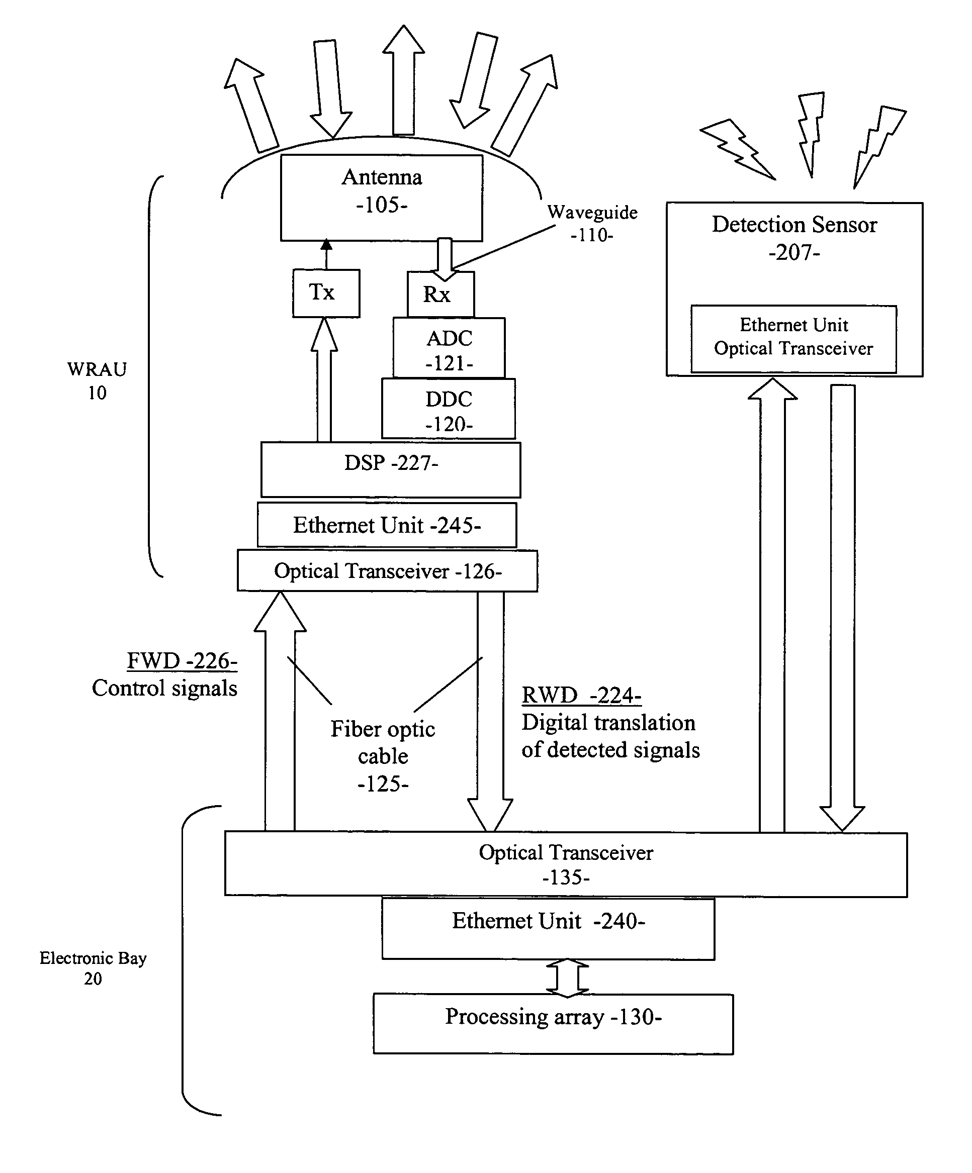
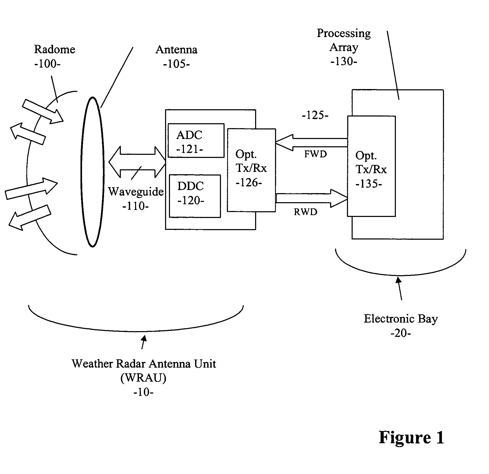
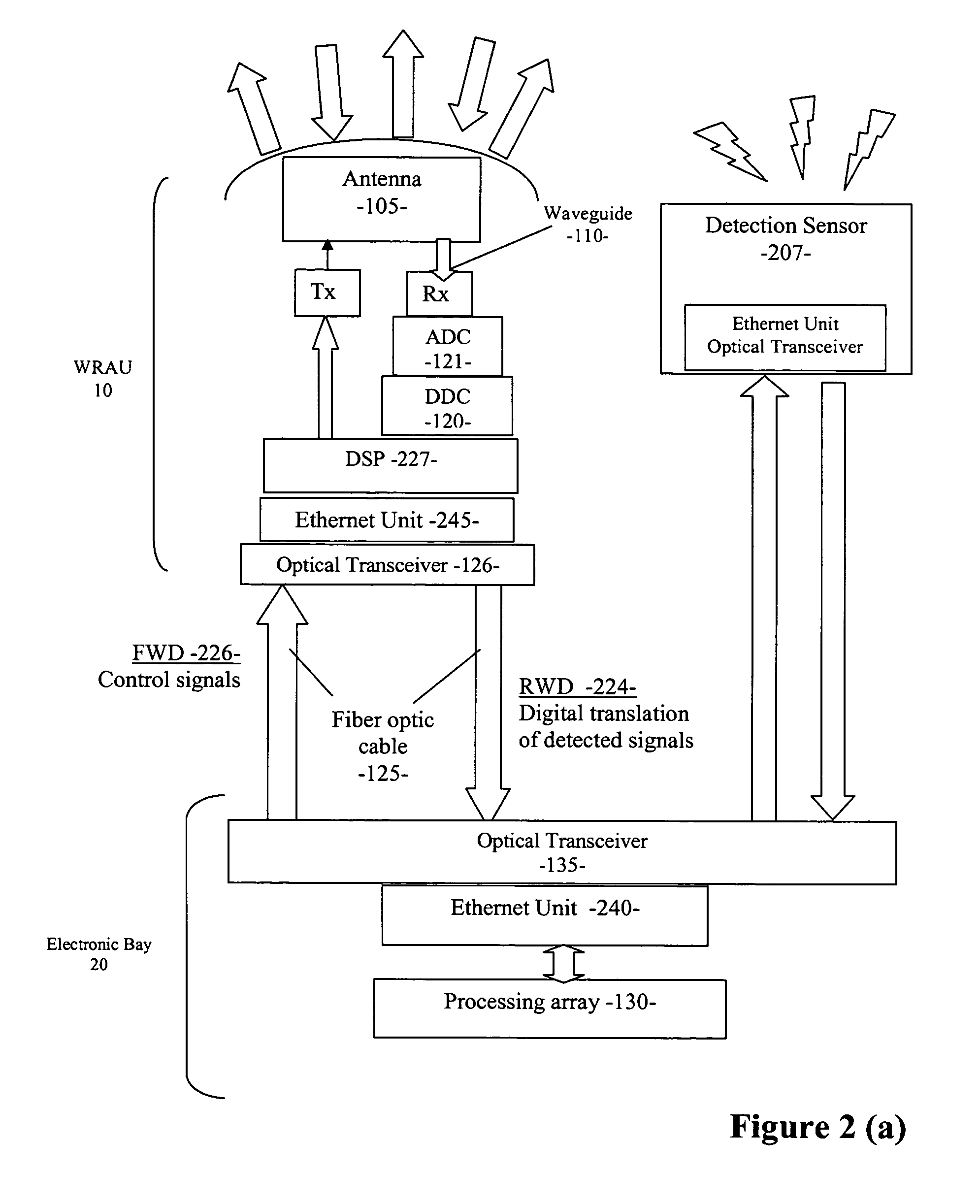
[0017]Reference is first made to FIG. 1, where a simplified diagram of the weather radar system in accordance with the present invention is shown. It should be noted that the simplified FIG. 1 only shows the functional blocks that are germane to the understanding of the present invention. As illustrated, an antenna unit 105 is placed inside the radome 100 at the front tip of an aircraft. A digital down-converter (“DDC”) 120 is coupled to the antenna unit 105 through a waveguide 110, forming a weather radar antenna unit 10 (“WRAU”). An analog-to-digital converter (“ADC”) 121 is provided to convert the received radar signals into their digital translation for data preparation and transmission. Through optical transceivers 126, 135 at both ends, a fiber optic cable 125 connects the WRAU 10 to a processing array 130 situated in the electronic bay 20 of the aircraft. The optical transceivers 126, 135 serve as an interface between the WRAU 10 and fiber optic cable 125, and between the fiber optic cable 125 and processing array 130, respectively.
[0018]In the forward path (“FWD”), i.e. from the electronic bay 20 to the WRAU 10, control signals are transmitted in order to operate the antenna 105. In the rearward path (“RWD”), from the WRAU 10 to the electronic bay 20, digital translation of the radar return signals are transmitted to the electronic bay 20, so that weather algorithm can be applied to the signals. The result of the weather data processing is communicated to the pilot via a display in the cockpit (not shown).
[0019]To illustrate the invention in more detail, reference is now made to FIG. 2, where a simplified block diagram of the weather radar system in accordance with the invention is shown. As shown, the reflected radar signals are picked up by the antenna 105 at the front tip of the aircraft. The reflected signals are transmitted through the waveguide 110 and received by a receiver Rx. The received signals are then converted to a digital format at baseband and decimated to generate a digital translation of the radar data, through the analog-digital converter (“ADC”) 121 and digital down-converter (“DDC”) 120. The digital data from the DDC 120 are formatted into data packets, as directed by the DSP 227, by the Ethernet unit 245 for transmission through the physical layer. Upon formatting and encoding, the radar return data are transmitted to the fiber optic cable 125 in the RWD path 224 and eventually to the processing array 130. After transmission through the fiber optic cable 125, the radar data are first received by the optical transceiver 135 and decoded by the Ethernet unit 240 so that the weather data can be analyzed by the processing array 130. As can be understood by those skilled in the art, the Ethernet unit 240 receives the RWD signals from the fiber optic cable 125 and ensures that they are optimally decoded and conveyed to the processing array 130. Currently, the Ethernet unit 240 is implemented with off-the-shelf LAN (“local area network”) components, such as SMSC LAN91C111 MAC & PHY, and Broadcom 5221 External PHY. It should be appreciated by those skilled in the art that other off-the-shelf parts LAN or Ethernet components are available for delivering data in accordance with the present invention.
[0020]In terms of the preferable data format for transmission through the fiber optic cable 125, currently UDP/IP datagrams are used. As is well known, UDP/IP datagrams are more basic and efficient than their more sophisticated cousin, TCP/IP. The UDP/IP protocol functions well in a simple point-to-point, uni-cast configuration, making it quite suitable for this avionics environment. TCP/IP, on the other hand, would have added more software complexity and overhead, thus gaining re-try capability at the expense of time delay. It should be noted that other transmission protocols can be readily utilized, provided that they meet the aforementioned basic design considerations of this avionics application, without the overdoing.
[0021]It should also be noted that instead of a pair of fiber optic cables, a full duplex fiber optic cable may be utilized to provide both the FWD and RWD signal paths. In comparison to signal paths formed by metal cabling, coaxial or non-fiber optic cabling, the fiber optic cable is known to be more advantageous in terms of weight and interference immunity.
[0022]Reference is still to the forward signal path of FIG. 2. The processing array 130, which has operation modes controllable by the pilot, generates control signals based on the modes selected by the pilot and propagates the control signals through the fiber optic cables 125 in the FWD direction 226 to the WRAU 10. The control signals, as can be appreciated by those skilled in the art, preferably control the sweeping angles of the antenna 105 or command the antenna 105 to certain operation mode, e.g. wind shear during takeoff and landing, or weather processing. The control signals are received by the optical transceiver 126/Ethernet unit 245, and decoded by the DSP 227 so that they can operate the antenna 105. By sending the control signals to the WRAU 10 through the fiber optic cable 226, the signals can be optimally conveyed, protected from RF interference.
[0023]By using the fiber optic cable 125, cable-induced EMI and RFI is eliminated. As such, the weather radar system may even be optionally implemented with additional sensor systems, for example, a lightning detection sensor 207 as shown in FIG. 2. It should be noted that virtually any detection sensor systems that require the detection signals to be transmitted to the electronic bay 20 for further processing may take advantage of the fiber optic cabling in accordance with the present invention. In one embodiment, as illustrated in FIG. 2 (b), the detected signals from the sensors 207, 250 are transmitted to the fiber optic cable 260, 262, respectively, connected between the detection sensor systems and the electronic bay 20. In other embodiment, such as one illustrated in FIG. 2 (c), the detection signals may be multiplexed with the cabling 125, such that the interface between the electronic bay 20 and the cabling is simplified by the use of the MUX 270. While FIGS. 2 (a)–(c) illustrate some exemplary interconnect schemes, those skilled in the art should be able to design the most effective cabling and interconnect schemes based on their system requirements. With conventional copper wiring, surface current or magnetic field would have easily traveled through and around any aperture on the aircraft, and be picked up by the copper wiring. In contrast, fiber optic cabling offers immunity against indirect effects of lightning and EMI between the antenna 105, DDC 120 and the processing array 130.
[0024]Reference is now turned to FIG. 3, where a simplified functional block diagram of the DDC 120 is further illustrated. Currently implemented in an FPGA (“field-programmable gate array”) device, the DDC is preferably designed to bridge the gap between the high-speed digital receiver ADC (FIG. 2, 121) and the digital receiver DSP (FIG. 2, 227). The DDC's main functions are to first convert the sampled received signal from the antenna to a digital format, i.e. in-phase/out-of-phase Quadrature samples, at baseband (blocks 310, 320). The received data are then filtered using a CIC (“cascaded integrator-comb”) filter and a FIR (“finite impulse-response”) filter (block 330), the operation of which are well-known in the area such as wireless base station technology. The sample rate of the filtered data is decimated from 9.3 GHz down to preferably about 1 MHz (block 340). After decimation, automatic gain control is implemented (block 350) and the digital down-converted data are formatted and sent to the antenna's DSP (FIG. 2, 227) in streams of 16-bit words containing the digital radar return information (block 370). Overall control of the DDC functions (FIG. 2, 120) is provided by the DSP (FIG. 2, 227) in order to maintain time coherency and synchronization in the WRAU 10.
[0025]Reference is now made to FIG. 4, where a simplified block diagram of the processing array 130 and Ethernet unit 240 in the electronic bay 20 is illustrated. At the electronic bay 20, among the processing array 130, the WxR DSP module 410 is implemented with Flash memory 412, SRAM 416 and a processor 420. Currently, the processor 420 is an Analog Devices ADSP-BF 532 (“Blackfin”) processor. The Ethernet unit 240 is connected to the EBIU (“external bus interface unit”) of the processor 420, such that the SMSC LAN91C111MAC & PHY 430 is addressable as a portion of the external memory of the processor. LVPECL is a “low-voltage positive emitter coupled logic” and is an electric signal path (through copper conductor) that connects the Broadcom 5221 PHY 440 to the backplane 450, thus to the optical transceiver 135 and fiber optic cable 125. MII is “media independent interface,” for providing a parallel interface between the Ethernet MAC to the PHY.
[0026]As described, the invention has the advantage of low protocol overhead while still being Ethernet-like, thus allowing use of off-the-shelf hardware and commonly available software. Further, the fiber optic cable link can electrically isolate the antenna/receiver from the electronic bay housing the weather and wind shear algorithms. The invention greatly reduces lightning-induced transients, an important consideration for new aircraft built using composite material.
[0027]In the foregoing specification, the invention has been described with reference to specific embodiments thereof. It will, however, be evident that various modifications and changes may be made thereto without departing from the broader spirit and scope of the invention. The specification and drawings are accordingly to be regarded in an illustrative rather than a restrictive sense.

PUM

no PUM

Description & Claims & Application Information

We can also present the details of the Description, Claims and Application information to help users get a comprehensive understanding of the technical details of the patent, such as background art, summary of invention, brief description of drawings, description of embodiments, and other original content. On the other hand, users can also determine the specific scope of protection of the technology through the list of claims; as well as understand the changes in the life cycle of the technology with the presentation of the patent timeline. Login to view more.

Similar technology patents

Multi-wavelength Brillouin optical time domain analyzer

InactiveCN103115632AIncrease total optical powerImprove signal-to-noise ratioSpecial purpose recording/indication apparatusOptical pathSignal-to-noise ratio (imaging)
Owner:NANJING UNIVERSTIY SUZHOU HIGH TECH INST +1

Classification and recommendation of technical efficacy words

  • Improve signal-to-noise ratio

Magnetic tape, its cleaning method, and optical servotrack forming/cleaning apparatus

InactiveUS7803471B1Improve signal-to-noise ratioDecreasing rate of fluctuationMagnetic materials for record carriersReconditioning/cleaning record carriersReflectivityMaximum rate
Owner:FUJIFILM CORP

System for generating thermographic images using thermographic signal reconstruction

ActiveUS20050008215A1Reduce size and complexityImprove signal-to-noise ratioCharacter and pattern recognitionMaterial flaws investigationSignal reconstructionThermographic imaging
Owner:THERMAL WAVE IMAGING

Hyper-spectral imaging methods and devices

InactiveUS20050270528A1Improve signal to noise ratioSmall bandwidthRadiation pyrometrySpectrum generation using diffraction elementsSpectral imagingLight spectrum
Owner:PLAIN SIGHT SYST
Why Eureka
Try Eureka