Cutter assembly for a grinder pump

a technology of grinder pump and cutter assembly, which is applied in the direction of machines/engines, grain treatment, gas current separation, etc., can solve the problems of clogging of the discharge material that is abrasive may gradually wear away the cutting edges of the grinding parts of the grinder pump, and the cutter design of the grinder pump is susceptible to binding problems

Active Publication Date: 2007-01-09
LIBERTY PUMPS
View PDF13 Cites 93 Cited by
  • Summary
  • Abstract
  • Description
  • Claims
  • Application Information

AI Technical Summary

Benefits of technology

[0028]In accordance with the present invention, there is provided a cutting assembly for size reduction of solids in a liquid to be pumped, the cutting assembly comprising a drive shaft rotatable in a first direction of rotation; a rotary cutter rotatably engaged with the drive shaft and comprised of at least a first cutting blade and a second cutting blade, each of the first and the second cutting blades including a leading cutting edge advanceable in the direction of rotation, the leading cutting edge formed at the junction of a leading side wall of the blade and a flat base of the blade; and a plate cutter comprised of an apertured wall including an inner discharge surface, and an outer cutter surface, the outer cutter surface including a plurality of cutting ports, each of the cutting ports comprising an entry opening, a first orifice passing though the apertured wall to the inner discharge surface, and a second orifice passing though the apertured wall to the inner discharge surface. The entry opening further comprises a first V-slice cutting edge and a second V-slice cutting edge intersecting at an angle directed opposite to the direction of rotation; a first cutting edge of the first orifice connected to the first V-slice cutting edge; and a second cutting edge of the second orifice connected to the second V-slice cutting edge. When the rotary cutter is rotated in the first direction of rotation, the cutting blades are rotationally advanced along the outer cutter surface of the plate cutter in a shearing action against the first V-slice cutting edge, the second V-slice cutting edge, the first cutting edge of the first orifice, and the second cutting edge of the second orifice of the cutting ports of the outer cutter surface of the plate cutter.
[0029]In accordance with the present invention, there is provided a grinder pump comprising a housing including a motor housing portion enclosing a pump motor, and a volute portion forming a pump volute, said pump volute enclosing a pump impeller; a volute cover; and a cutting assembly for size reduction of solids in a liquid to be pumped, said cutting assembly as recited in the immediately foregoing description. In one embodiment, the plate cutter of the cutting assembly is integrally formed into the volute cover of the grinder pump.

Problems solved by technology

The cutter design of this pump is susceptible to binding problems because material is cut in large pieces and such material can become wedged either in the cutter or between the impeller edges and the intake spiral cutting plate.
Also the discharge of this pump can become clogged under severe operating conditions.
Such solids may have a wide variety of properties that are adverse to the operation of the pump, including high shear strength, abrasiveness, hardness, elasticity, and / or plasticity.
Materials that are abrasive may gradually wear away the cutting edges of the grinding parts of the pump.
Materials that have high shear strength and / or high hardness may shatter or deform the cutting edges of the grinding parts of the pump.
Instead of being cleanly cut up into smaller parts, these materials may deform and “gum up” or otherwise clog the grinding pump.
Fibrous, string-like materials suspended in a liquid are particularly difficult to shred with a grinder pump.
On a local scale on the order of the fiber diameter, these materials have a relatively small cross section and are more difficult to shear by the cutting edges.
In addition, the relatively long length and elastic or plastic properties often cause them to wrap around the internal pump components parts such as a cutting disk, an annular ring and a pump shaft.
Numerous prior art grinder pumps are not capable of rejecting such hard objects, rendering them especially vulnerable to jamming at start up.
In addition, numerous prior art grinder pumps are not capable of grinding a sudden heavy load of fibrous material that may be encountered.
Such grinder pumps will bog down and clog on the heavy fibrous load, or suddenly jam if a hard solid object is introduced into the cutting parts of the pump.

Method used


Image

  • Cutter assembly for a grinder pump
  • Cutter assembly for a grinder pump
  • Cutter assembly for a grinder pump

Examples


Embodiment Construction

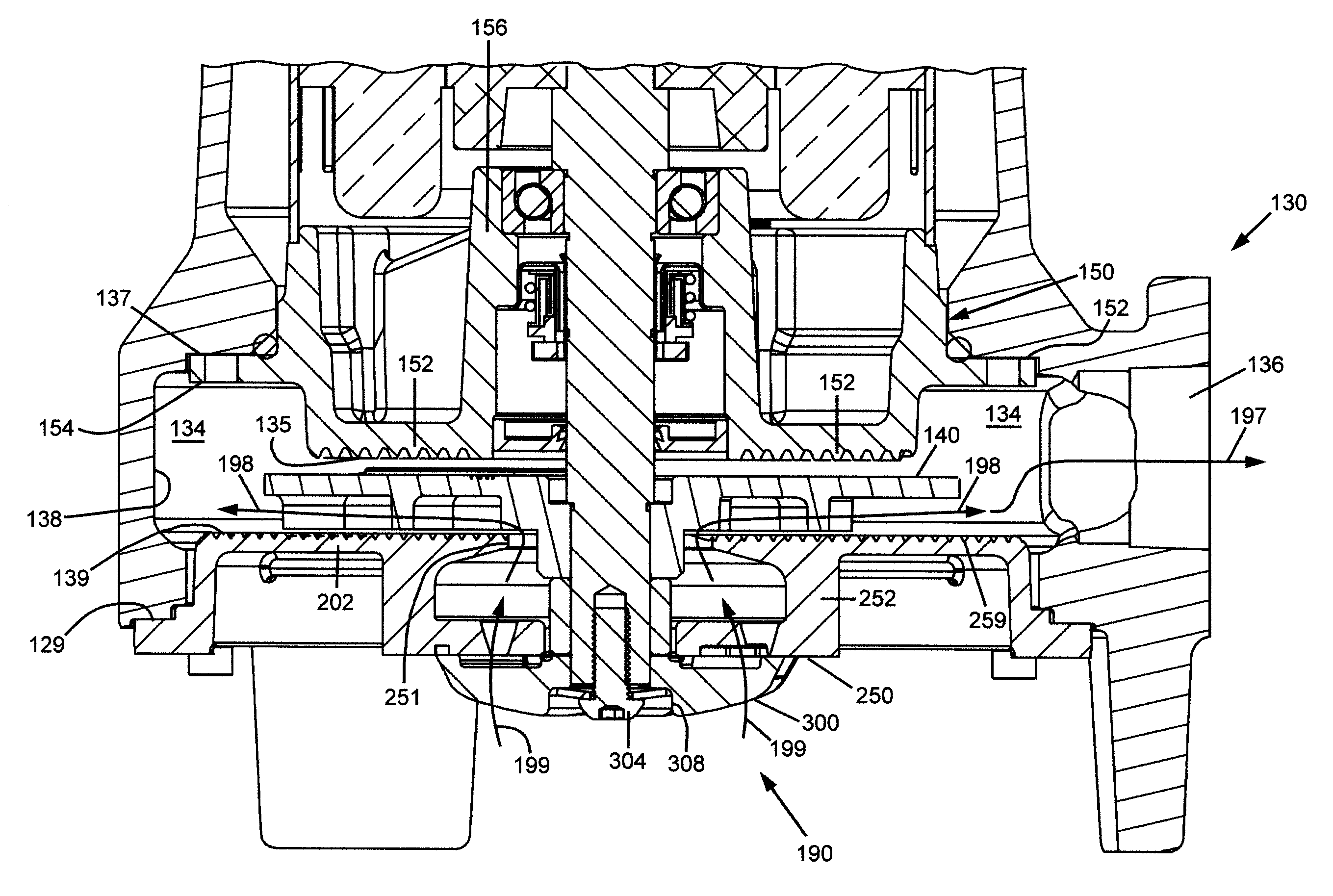
[0046]For a general understanding of the present invention, reference is made to the drawings. In the drawings, like reference numerals have been used throughout to designate identical elements. In describing grinding assemblies for size reduction of solids in liquids to be pumped, a variety of terms are commonly used in the description. A rotating blade device is commonly referred to as a grinder impeller or a rotary cutter. Herein, such terms may used interchangeably and are to be understood as meaning the same thing. It is also to be understood that a grinder impeller as used herein is distinct from a pump impeller, which is commonly understood to be a rotating vaned disc that draws a liquid into a central region thereof and centrifugally discharges such liquid outwardly in a pumping action.

[0047]An overall cutting assembly for size reduction of solids in liquids to be pumped is often referred to as a grinding impeller and cutter assembly, a cutting assembly, a cutter assembly, a...


PUM


Abstract

A cutting assembly for a grinder pump comprised of a rotary cutter rotatable against an opposing plate cutter. The cutting edges of the plate cutter include a plurality of V-slice cutting teeth, which create bridging spaces to pinch material which is being sucked in to ports and begin cutting along the V-slice and then for cut material to pass through and onward into the volute of the pump. The rotary cutter has a ground edge with a rake angle which shears the gathered material in cooperation with the cutting edges of the plate cutter. A grinder pump including the cutter assembly is also disclosed.

Description

[0001]This invention relates in one embodiment to a grinder pump, and more particularly to such a pump with a grinding impeller and cutter assembly for grinding, cutting, shredding, and / or comminuting suspended solids in a liquid, and for simultaneously pumping a slurry of such suspended solids.FIELD OF THE INVENTION[0002]A grinding impeller and cutter assembly for a grinder pump for reducing the size of suspended solids in a liquid stream and simultaneously pumping such liquid stream.BACKGROUND OF THE INVENTION[0003]Grinder pumps are commonly used in liquid transfer applications that require the grinding of large solid or semisolid materials contained in a liquid, in order to grind, cut, or shred such materials. Ultimately, such solid or semisolid materials are reduced in size to the point where a slurry is formed, which is more easily pumped or otherwise transported, and which is more disposable than the solids themselves. Grinder pumps typically have an axial inlet connected to a...

Claims


Application Information

Patent Timeline
Patent Type & Authority Patents(United States)
IPC IPC(8): B02C23/36
CPCB02C18/0092F04D7/045F04D3/02
Inventor RITSEMA, STEPHEN T.
Owner LIBERTY PUMPS
Why Eureka
Try Eureka