Receiver for high rate digital communication system

a digital communication system and receiver technology, applied in the field of receivers for high-rate digital communication systems, can solve the problems of limiting the maximum bit rate of the system, linear and non-linear signal dispersion, and impairment of lightwave systems

Inactive Publication Date: 2007-01-09
LUCENT TECH INC +1
View PDF8 Cites 11 Cited by
  • Summary
  • Abstract
  • Description
  • Claims
  • Application Information

AI Technical Summary

Benefits of technology

[0010]It is an object of the invention to provide, in particular with regard to the afore-discussed state of the art, a new and improved approach for processing a received transmission signal adapted to be used in high rate communication systems with

Problems solved by technology

In general, transmission impairments in lightwave systems mainly results from linear and non-linear signal dispersion, noise and intermodulation in case of multiple signals.
Dispersion broadens the width of pulses, resulting in inter-symbol-interference (ISI) which limits the maximum bit rate of the system.
Furthermore, limited laser and receiver bandwidth and an enlarged spectral shape of the transmitted pulses due to a laser phase noise increase ISI.
Such communication systems usually using standard-mono-mode fibers, erbium-doped fiber amplifiers and non-coherent optical receivers are still disturbed by non-linear dispersion and signal dependent non-Gaussian noise resulting in a decreased SNR which is additionally decreased by reduced signal power due to wavelength multiplexing or longer coverage distances.
However for

Method used


Image

  • Receiver for high rate digital communication system
  • Receiver for high rate digital communication system
  • Receiver for high rate digital communication system

Examples


Embodiment Construction

[0031]For a better understanding of the subsequent exemplar description of the invention and especially to easier ensure the inventive approach, certain requirements and assumptions with regard to preferred inventive embodiments and / or applications are made in advance.

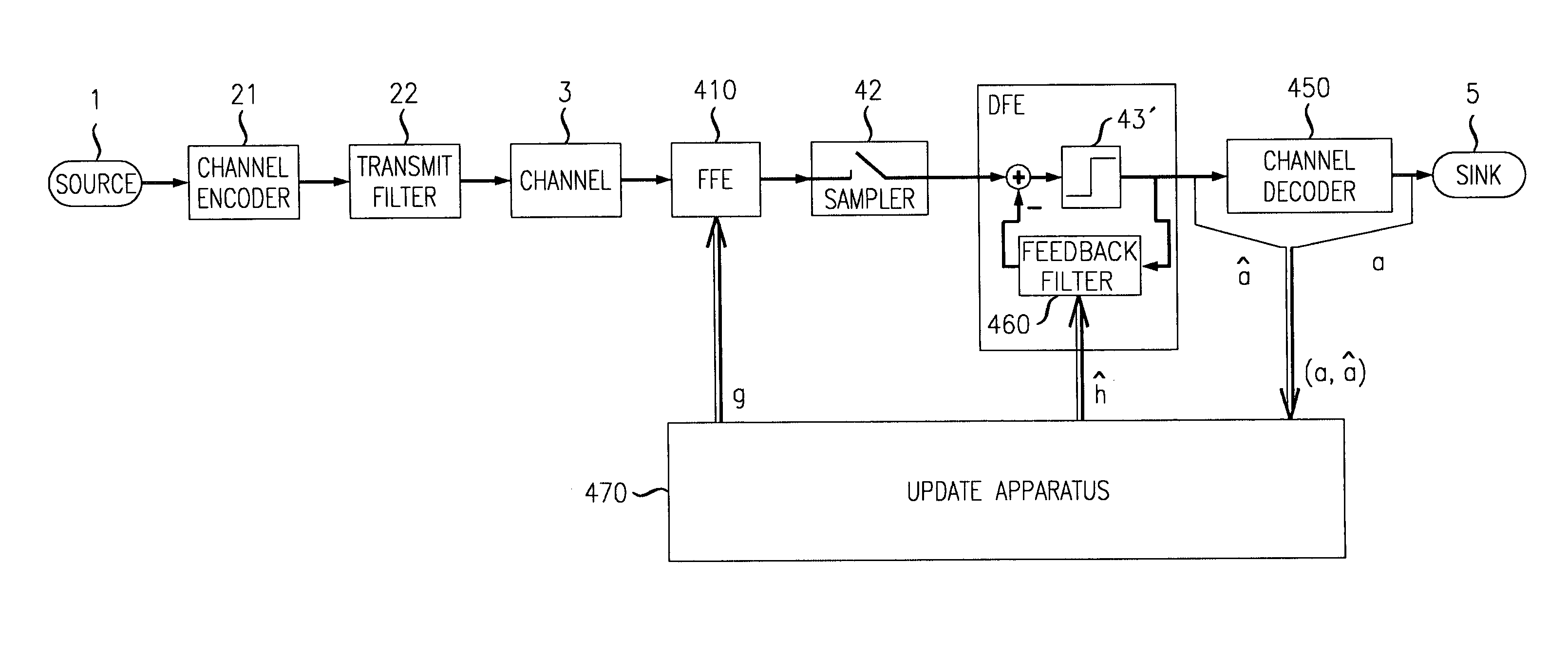
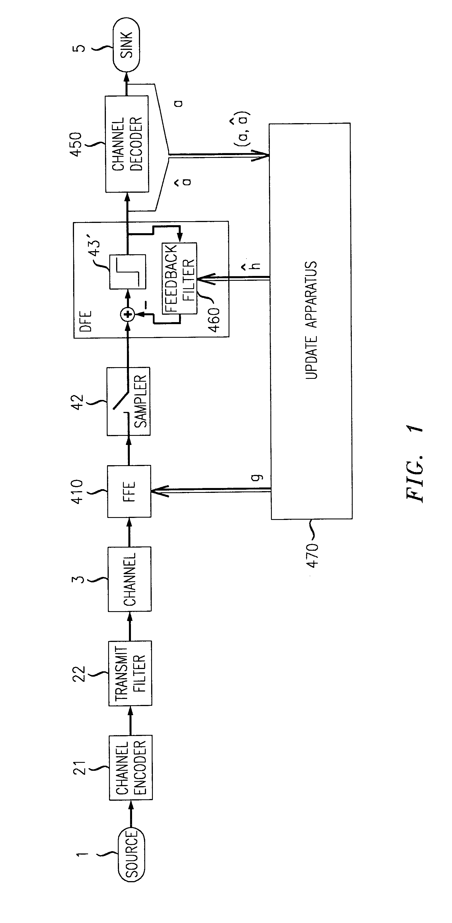
[0032]Regarding first FIG. 4, a generic digital transmission system is schematically depicted having fundamental components, such as a digital data source 1, a transmitter 2, a transmission channel 3, a receiver 4 and a data sink 5.

[0033]The transmitter 2 maps digital source data onto specific physical signals, such as for example voltage pulses. Within the transmission channel 3 these signals are corrupted by distortions and disturbances like noise.

[0034]According to the preferred embodiments of the invention and hence, within preferred applications of the inventive approach, the transmission channel comprises an optical channel such as an optical fiber so that the transmitter 2 is comprising an electrical-to-optical ...


PUM


Abstract

A system and method for processing received transmission signal(s) adapted to be used in high rate communication systems without impairing the received signal energy and without additional expensive components. The system and method are adapted to transmission system(s) having at the receiver-side a compound system of a feed-forward equalizer (FFE) and a subsequent decision feedback equalizer (DFE). A feed forward equalization and/or a decision feedback equalization is performed on the received high rate signal by deriving adaptation information from the equalized signal after a signal decision is performed for adjusting all intended feed forward equalization and/or decision feedback equalization coefficients and/or table entries in dependence on said information.

Description

FIELD OF THE INVENTION[0001]The invention relates to a method of processing a received high rate transmission signal and to a receiver for high rate digital communication systems.BACKGROUND OF THE INVENTION[0002]In general, transmission impairments in lightwave systems mainly results from linear and non-linear signal dispersion, noise and intermodulation in case of multiple signals. Dispersion broadens the width of pulses, resulting in inter-symbol-interference (ISI) which limits the maximum bit rate of the system. In particular the mono-mode fiber characteristics of chromatic dispersion caused by frequency dependent delay and attenuation and of polarization mode dispersion (PMD) denoting the propagation of two polarization modes with different frequency dependent signal delays superimposing at the photodiode result in linear and non-linear ISI.[0003]Furthermore, limited laser and receiver bandwidth and an enlarged spectral shape of the transmitted pulses due to a laser phase noise ...

Claims


Application Information

Patent Timeline
IPC IPC(8): H03H7/30H03D1/24H03H21/00H04L25/03
CPCH03H21/0012H04L2025/03617H04L2025/0349H04L2025/03477
Inventor DITTRICH, ANDREASSAUER-GREFF, WOLFGANG EMIL MICHAELURBANSKY, RALPH STEFFEN
Owner LUCENT TECH INC
Why Eureka
Try Eureka