RF quadrupole systems with potential gradients

a potential gradient and quadrupole technology, applied in the field of two-dimensional quadrupole systems, can solve the problems of difficult to generate a desired dc electric field along the axis, unable to propagate the rf voltage at the end along the wires sufficiently quickly, and unable to generate a small dc voltage drop along the wires, so as to increase the ion acceptance

Active Publication Date: 2007-01-16
BRUKER DALTONIK GMBH & CO KG
View PDF13 Cites 31 Cited by
  • Summary
  • Abstract
  • Description
  • Claims
  • Application Information

AI Technical Summary

Benefits of technology

[0021]The quadrupole system can particularly consist of hyperbolic lengthy electrodes, the hyperbolic surfaces being arranged diagonally opposite each other. Compared with the round-rod systems frequently used today, a hyperbolic quadrupole system of this type has the advantage that, firstly, the ions do not escape as a result of nonlinear resonances and, secondly, (in the mode where DC voltages are not superimposed with opposite polarity on the two RF phases, a so-called “RF-only” mode) the repelling pseudopotentials have the same parabolic rise from the axis in all radial directions, i.e., they supply the same repelling forces from all radial directions. Escape of ions via too low a pseudopotential barrier between the pole rods through laterally deflecting collision cascades is almost completely prevented. A hyperbolic system of this type is particularly advantageous as a collision cell for ion fragmentations.

Problems solved by technology

Furthermore, the resistance must not be too high, otherwise the RF voltage fed at the ends cannot propagate along the wires sufficiently quickly.
It is therefore only possible to generate rather small DC voltage drops along the wire.
Also, it is difficult to generate a desired profile of the DC electric field along the axis.
These quadrupole systems made from wires are difficult to produce, however, and not very precise, but they do provide a simple way of generating an axial DC field by generating voltage drops along the wires.
These devices are, however, not particularly satisfactory: System (a), comprising nonconducting rods with resistive coating, conducts the RF voltage only in a limited way (similar to the system made of four resistance wires), so that the RF voltage varies along the system, an occurrence which is extraordinarily damaging for some applications; or the resistive coating must have an extremely low resistance.
System (b), made of thin ceramic tubes (according to the specification, tube walls some 0.5 to 1 millimeter thick) with inner metal coating to generate the RF fields and outer high-resistance layer for the DC voltage drop, is also very disadvantageous.
This invention is not successful in practice: It is not only the fact that the authors underestimate the strength of the RF attenuation when penetrating the high-resistance layer, but also that high dielectric losses occur in the material of the ceramic tubes as a result of the RF, so that the system in the vacuum becomes hot within a short time and can even begin to glow.
In addition, the round rods made of the thin ceramic tubes are mechanically not particularly stable.
This technology seems to us to be quite unusable; as far as we know it has never been used in practice.
Inexpensive round-rod systems were always considered good enough for the collision chambers, expensive hyperbolic systems were not used at all.
Round-rod systems contain octopole and higher even-numbered multipole fields of considerable strength superimposed on the quadrupole field, leading to a distortion of the ion oscillations in the radial direction and hence to the formation of higher harmonics of the ion oscillation.
For ions lying damped in the axis of the system, the resonances are not effective since there, the higher multipole fields and hence the overtones (higher harmonics) disappear.
These ions are therefore inevitably subjected to the phenomenon of non-linear resonances if they fulfil one of the numerous resonance conditions.
Moreover, round-rod systems have the further disadvantage that the pseudopotential barrier between the rods is quite low (in commercially available systems only some ten to twenty volts) and can easily be overcome by ions with an energy of 50 electron-volts, the minimum usually required for fragmentation processes, by means of a random, laterally deviating collision cascade.
The larger angles of deflection of a small number of collisions are not able to compensate each other statistically as effectively as the large number of smaller angles of deflection in the case of a very light collision gas.

Method used


Image

  • RF quadrupole systems with potential gradients
  • RF quadrupole systems with potential gradients
  • RF quadrupole systems with potential gradients

Examples


first embodiment

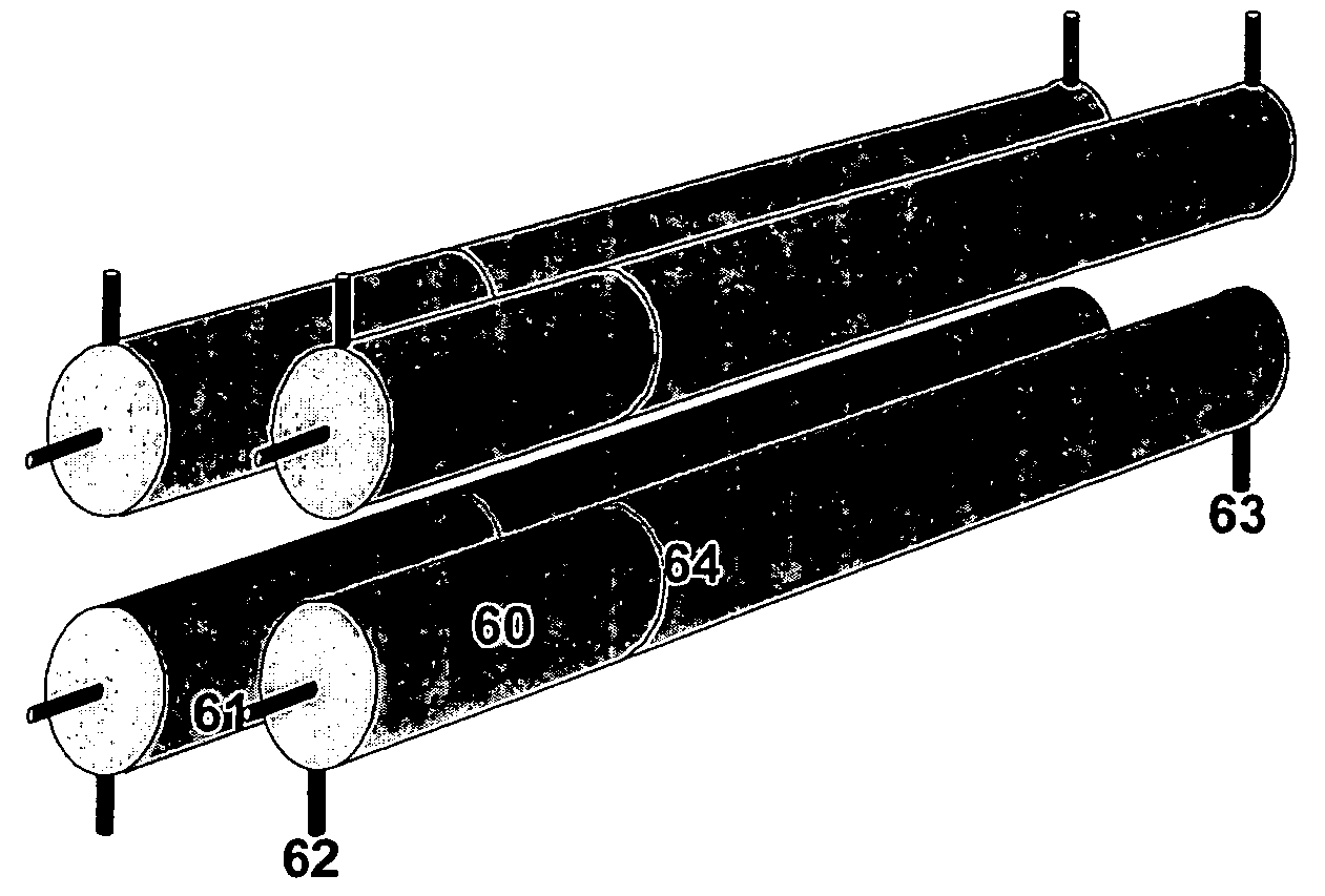
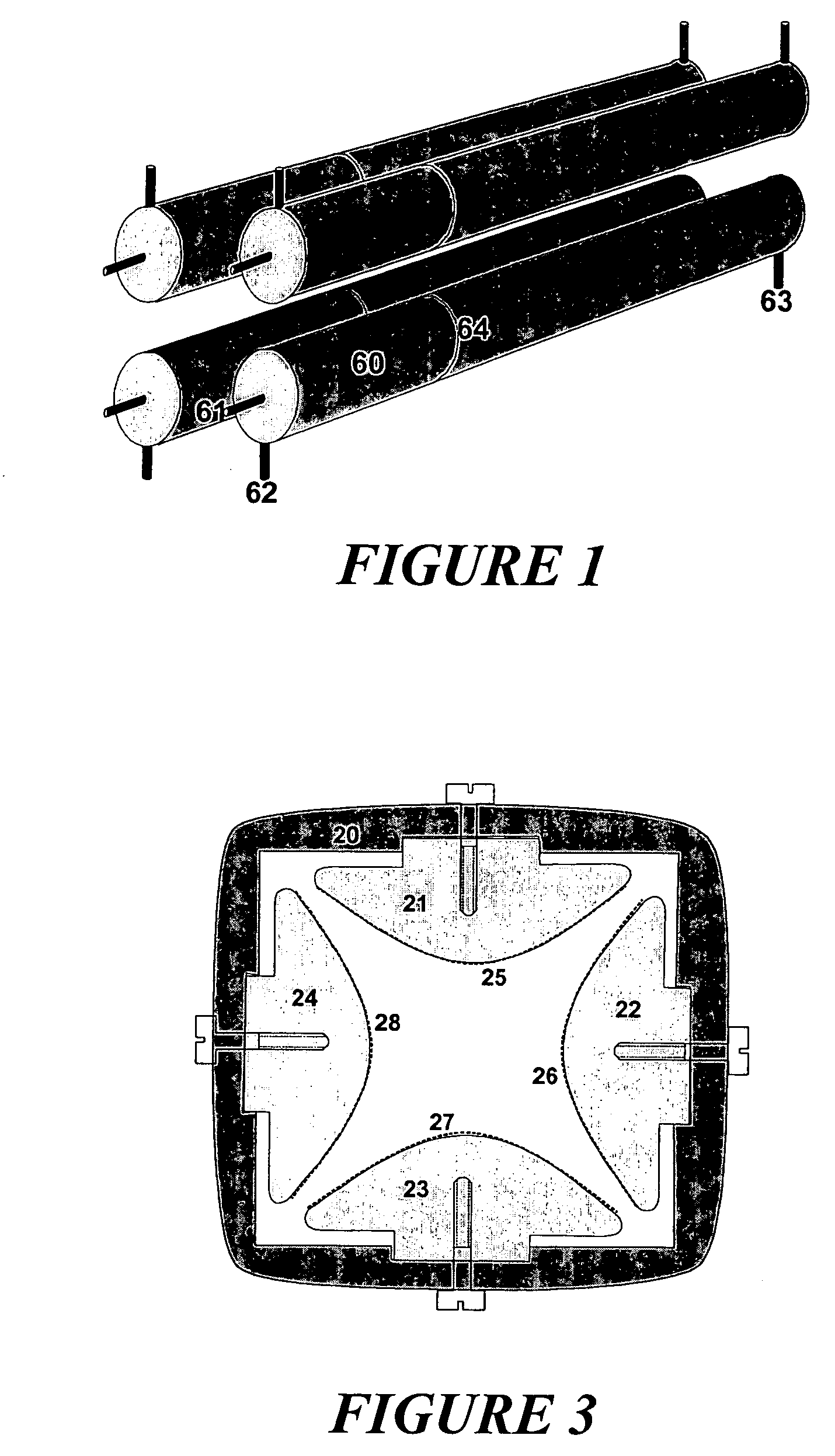
[0028]A first embodiment as shown in FIG. 1 consists of a round-rod quadrupole system whose rods (60) are coated with a thin layer of metal over a thin insulating layer. The thin layers of metal are connected via the schematically represented connectors (62, 63) with DC potentials on which, according to the invention, the same phase of the RF voltage is superimposed. The lengthy bulk electrodes themselves are connected via the connectors (61) to a DC potential superimposed with the two phases of the RF voltage. Opposing pairs of the electrodes and their thin metal layers each carry DC voltages superimposed by the same phase of the RF voltage. At the location (64), the thin metal layers are connected to the round-rod electrodes beneath; the DC potential of the round rods therefore lies across the thin metal layers. It is therefore possible to produce different field gradients on either side of these through-hole connections (64).

second embodiment

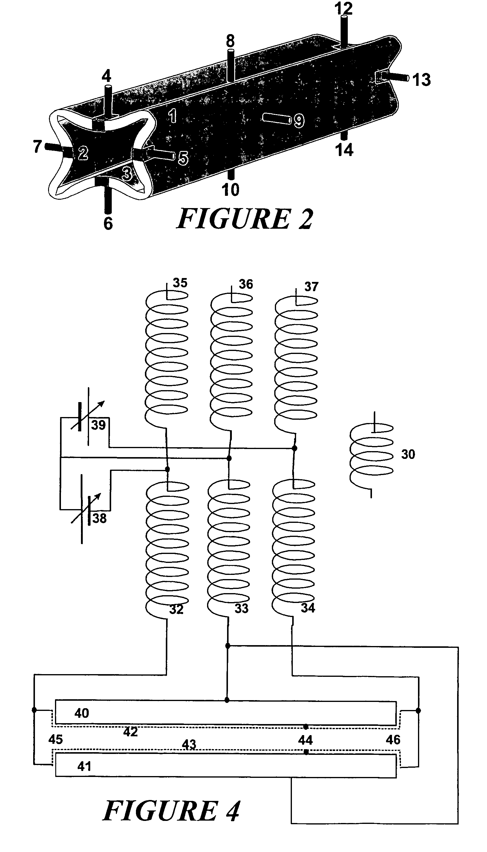
[0029]A second embodiment as shown in FIG. 2 presents a precision quadrupole mass filter comprising a glass body (1) with four hyperbolic electrode sheets (2, 3) fused on using a hot molding process. A quadrupole mass filter of this type can be produced in accordance with patent specification DE 2737903 (U.S. Pat. No. 4,213,557). It is extraordinarily precise at maintaining all dimensions. The hyperbolic electrode sheets (2, 3) are coated with a layer of a varnish with good insulating properties, for example a polyimide varnish, only a few micrometers thick. When dry, a very thin layer of metal, e.g., chromium or tungsten, only a few nanometers thick can be vapor deposited onto the insulating layer in a vacuum. It is thus possible to produce reproducibly a layer with a resistance of five kilohms, in other cases also with 50 kilohms. The ends of these layers are bonded by means of an electrically conductive varnish to connectors, as shown in FIG. 1.

[0030]The vapor-deposited thin laye...

third embodiment

[0033]A third embodiment is shown in FIG. 3. Here, individual hyperbolic electrodes (21, 22, 23, 24) are made of aluminum and then strongly anodized to generate an oxide layer. The thin metal layers (25, 26, 27, 28) are then vapor deposited onto the oxide layer of the hyperbolic surface. The electrodes are equipped with threads and screwed into an insulating holder (20), which can be a precisely formed glass body produced in a hot-replica technique.

[0034]As those skilled in the art will recognize, the lengthy electrodes of the quadrupole systems can also be made of other electrode materials, which then can be coated with an insulating oxide layer and, of course, it is also possible to use an insulating varnish or any other type of insulating coating here. It is also possible to use other types of insulating frames such as ground ceramic rings to hold the electrodes. Those skilled in the art will also be aware that, for precision quadrupole systems, special measures such as repeated ...


PUM


Abstract

The invention relates to two-dimensional quadrupole systems along whose axis an axial DC field is superimposed. The invention involves coating the hyperbolic or cylindrical surfaces of quadrupole systems with thin insulating layers and metal films thereupon and generating axial potential gradients or saddle ramps using appropriate electrical supply of DC potentials and superimposed RF voltages to the metal films. Systems of this type can be used in a plurality of ways, ranging from mass filters with high transmission to fragmentation cells with extremely low ion losses.

Description

FIELD OF THE INVENTION[0001]The invention relates to two-dimensional quadrupole systems along whose axis an axial DC field is superimposed.BACKGROUND OF THE INVENTION[0002]There has been a long search for radially-repelling ion confinement systems with axially superimposed DC electric fields for various types of applications: for ion guides, for the generation of monoenergetic ion beams, and in particular for collision cells used to fragment and thermalize ions. In such systems it is possible, for example, to not only fragment ions by means of collisions but also to thermalize them, the ions being transported to the ion exit at the end of the system either subsequently or simultaneously by a weak axial DC field. Even for high-resolution mass filters with two-dimensional quadrupole RF fields, a DC potential profile along the axis would offer completely new possibilities, particularly with respect to high transmission and operation at a high damping gas pressure. The term “two-dimensi...

Claims


Application Information

Patent Timeline
Patent Type & Authority Patents(United States)
IPC IPC(8): H01J49/42B01D59/44G21K1/093H01J37/141H01J49/04H01J49/06H01J49/44
CPCH01J49/443H01J49/04H01J49/06
Inventor WEISS, GERHARDFRANZEN, JOCHENSTOERMER, CARSTEN
Owner BRUKER DALTONIK GMBH & CO KG
Why Eureka
Try Eureka