Eureka AIR delivers breakthrough ideas for toughest innovation challenges, trusted by R&D personnel around the world.

Inductive device and method for producing the same

a technology of inductive devices and inductive chambers, applied in the field of inductive devices, can solve the problems of inconvenient increase, poor mass production efficiency, increased cost, etc., and achieve the effects of reducing cost, high yield, and good yield

Active Publication Date: 2007-01-23
TDK CORPARATION
View PDF23 Cites 4 Cited by
  • Summary
  • Abstract
  • Description
  • Claims
  • Application Information

AI Technical Summary

Benefits of technology

[0010]Under such circumstances, an object of the invention is to provide an inductive device of high performance and narrow tolerance.
[0011]Another object of the invention is to provide a method for producing an inductive device with high yield and high mass production efficiency.
[0013]The present invention realizes a high-performance narrow-tolerance inductive device which can be mass-produced with high yield.
[0014]When an inorganic sintered core board is used as a core board, good yield and reduction in cost can be achieved because the core board is little deformed due to thermal shrinkage, warp, etc. and excellent in dimensional stability so that positional displacement at the time of lamination can be particularly suppressed. When a porous ceramic substance is used as the material of the inorganic sintered core board, good handling can be obtained because the inorganic sintered core board is good in cutting characteristic and higher in strength than the organic board used singly. When a magnetic substance is used as the material of the inorganic sintered core board, there is an advantage in that helical coils can be coupled to each other firmly when a transformer is formed because magnetic permeability can be increased.

Problems solved by technology

a: Performance of a coil is good but tolerance has an inconvenient tendency toward increase.
b: Poor mass production efficiency causes increase in cost because of necessity of winding operation.

Method used


Image

  • Inductive device and method for producing the same
  • Inductive device and method for producing the same
  • Inductive device and method for producing the same

Examples


first embodiment

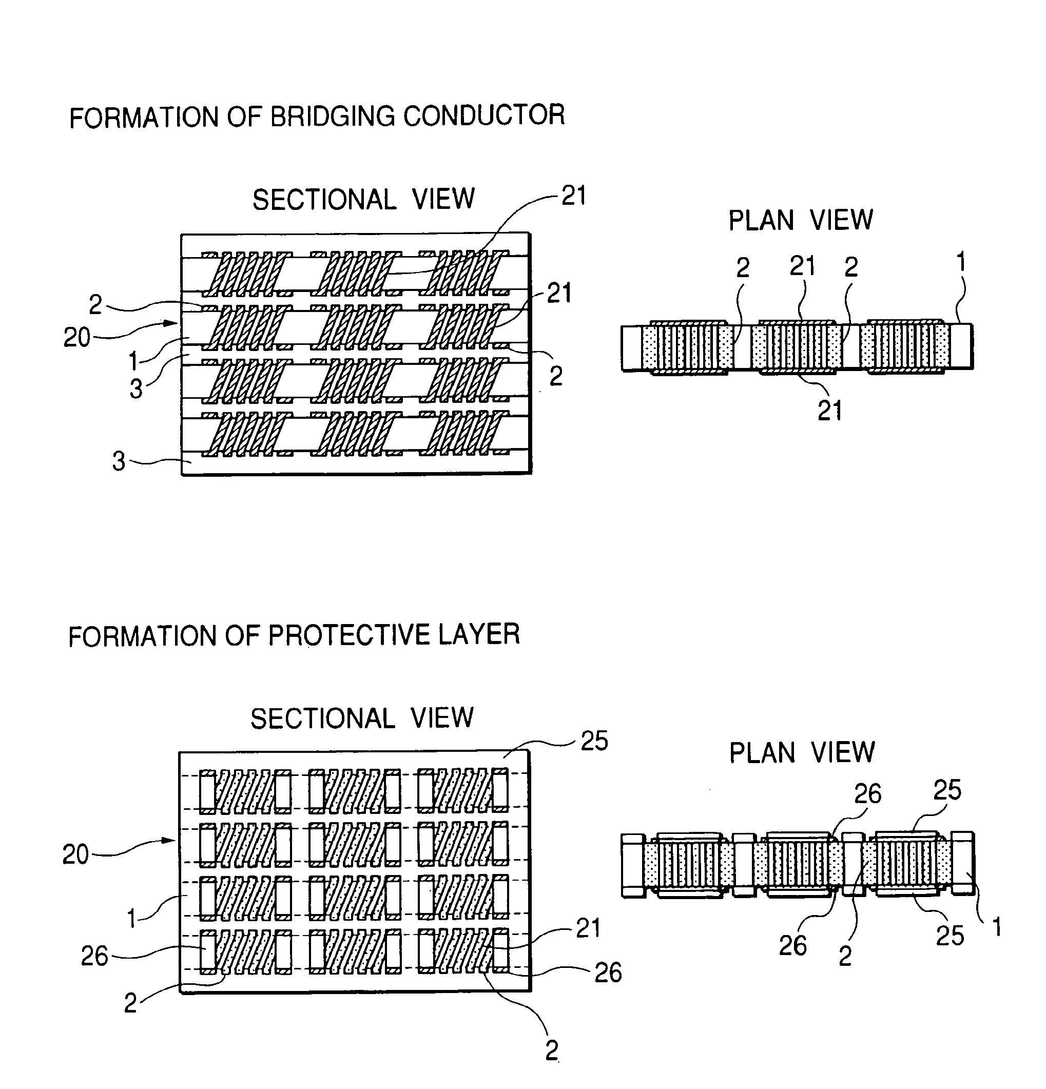
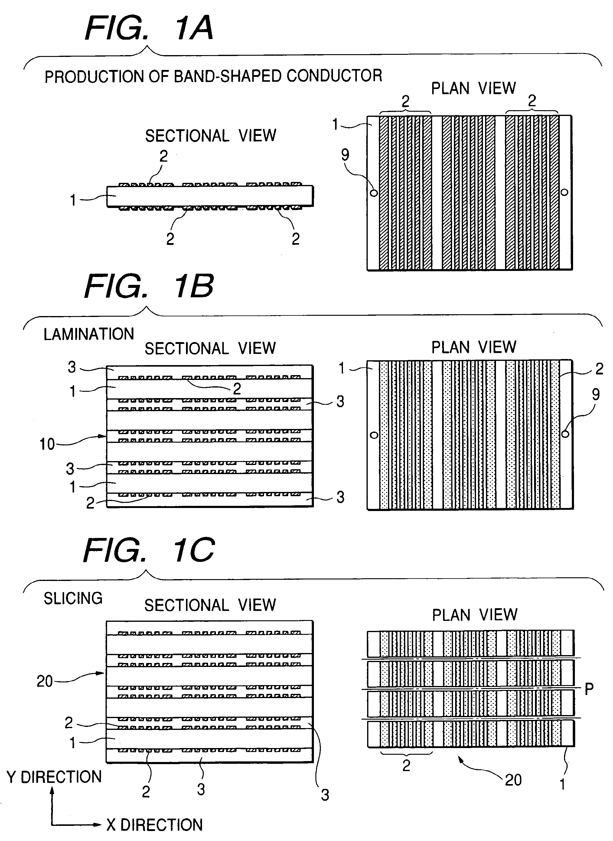
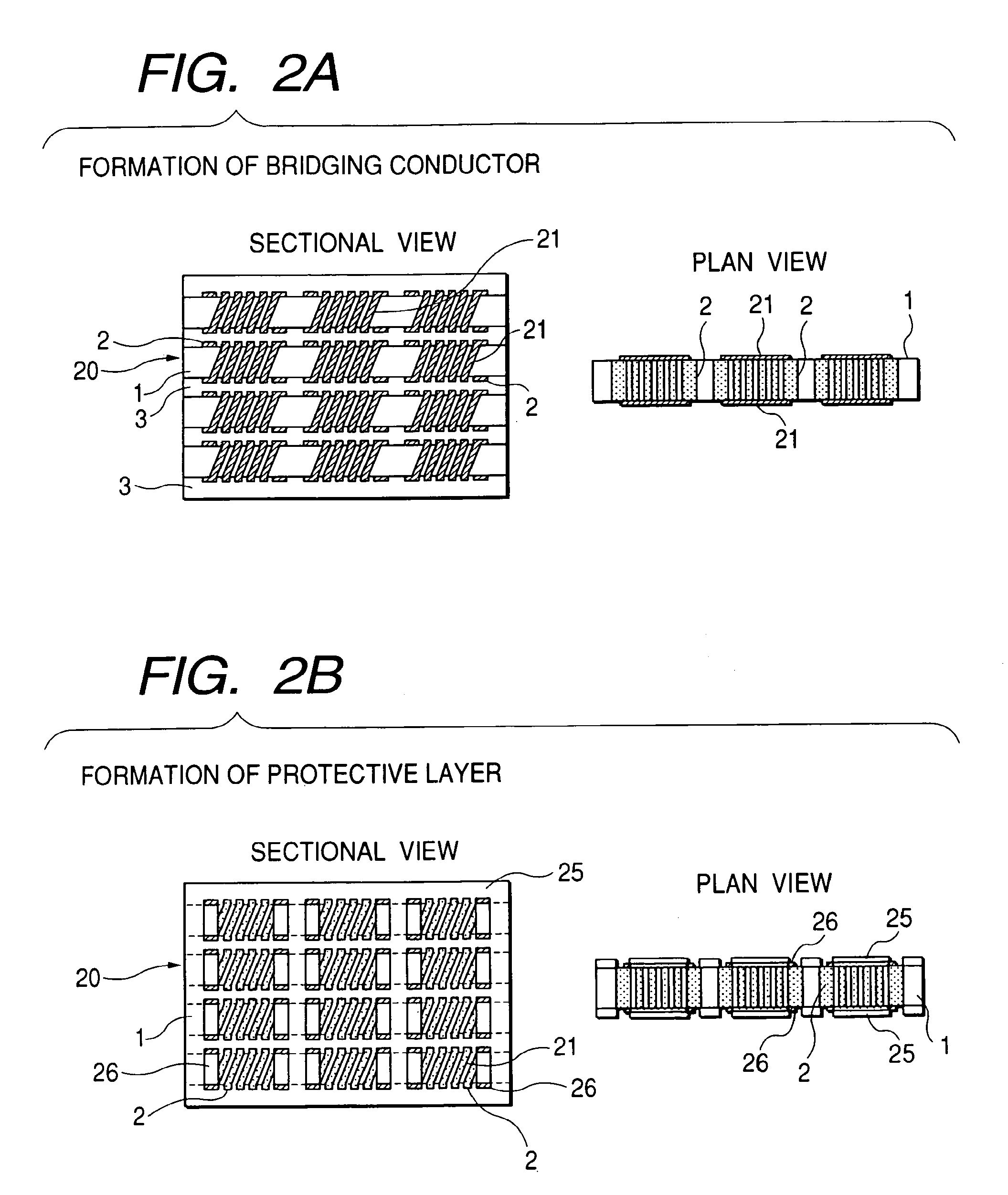
[0026]A first embodiment of the invention will be described with reference to FIGS. 1A to 1C and FIGS. 2A to 2D. First, in the band-shaped conductor production step shown in FIG. 1A, an organic core board 1 having a core material is prepared and a plurality of parallel band-shaped conductor patterns 2 are formed on front and rear surfaces of the board 1 by use of a plurality of front and rear alignment through-holes 9 formed in the board 1.

[0027]The core material-including organic core board 1 is a resin board reinforced with a core material impregnated with a resin. Examples of the core material include glass cloth, resin cloth such as Kepler, and a porous sheet of a fluororesin (trade name: Teflon). Additives may be preferably added to the resin, for example, to control a linear expansion coefficient and improve electrical characteristic. Examples of the additives include spherical silica filler, ferroelectric powder such as barium titanate powder, and ferrite powder (composite fe...

second embodiment

[0048]A second embodiment of the invention will be described with reference to FIGS. 3A to 3C and FIGS. 4A to 4D. First, in the band-shaped conductor production step shown in FIG. 3A, a core board 1A is prepared and a plurality of parallel band-shaped conductor patterns 2 are formed on a surface of the board 1A.

[0049]A resin board or a resin board reinforced with a core material impregnated with a resin can be used as the core board 1. Examples of the core material include glass cloth, resin cloth such as Kepler, and a porous sheet of a fluororesin (trade name: Teflon). Additives may be preferably added to the resin as a main material, for example, to control a linear expansion coefficient and improve electrical characteristic. Examples of the additives include spherical silica filler, ferroelectric powder such as barium titanate powder, and ferrite powder (composite ferrite). For production of high-frequency parts such as a high-frequency coil, a high-Q low-ε material such as a vin...

third embodiment

[0057]A third embodiment of the invention will be described with reference to FIGS. 5A to 5D and FIGS. 6A to 6D. First, in the band-shaped conductor production step shown in FIG. 5A, an organic core board 1 having a core material is prepared and a plurality of parallel band-shaped conductor patterns 2 are formed on front and rear surfaces of the organic core board 1 by use of a plurality of front and rear alignment through-holes 9 formed in the organic core board 1. This step is the same as in the first embodiment.

[0058]Then, in the first lamination step shown in FIG. 5B, interlayer electrically insulating layers (prepregs or adhesive sheets) 4 are put on front and rear surfaces of the organic core board 1 having the parallel band-shaped conductor patterns 2 formed on its front and rear surfaces in the band-shaped conductor production step. The interlayer electrically insulating layers 4 and the organic core board 1 are laminated integrally by pressing, heating, etc. In this manner,...


PUM

PropertyMeasurementUnit
thickaaaaaaaaaa
heightaaaaaaaaaa
heightaaaaaaaaaa

Abstract

A core material-including organic core board or inorganic sintered board 1 having a plurality of band-shaped conductor patterns 2 formed on its front and rear surfaces is sliced in a direction crossing the band-shaped conductor patterns 2. End portions of the band-shaped conductor patterns 2 exposed on each of cut surfaces of the core board 1 are connected to one another by bridging conductor patterns formed on the cut surfaces. In this manner, at least one helical coil is provided. The inner diameter of the helical coil can be kept constant while coil pitch accuracy can be kept good.

Description

BACKGROUND OF THE INVENTION[0001]The present invention relates to an inductive device using a magnetic induction phenomenon of a coil, a transformer, a common mode choke coil, etc. and a method for producing the inductive device. Particularly it relates to a structure of an inductive device permitting mass production of high-performance narrow-tolerance devices and a method for producing the inductive device.[0002]The method for producing this type inductive device has been heretofore roughly classified into the following processes.(1) Winding Process[0003]This is a most general process in which a wire is wound on a magnetic or non-magnetic core.(2) Building-up Process[0004]This is a process described in JP-A-2002-134321. In this process, electrically insulating boards having coil conductors provided to form part of a helical coil and electrically insulating layers are laminated alternately to form a helical coil.[0005]The processes have the following problems respectively.(1) Windi...

Claims


Application Information

Patent Timeline
Patent Type & Authority Patents(United States)
IPC IPC(8): H01F5/00H01F5/06H01F41/34H01F17/00H01F17/02H01F41/04H01L23/64
CPCH01F17/0013H01F17/0033H01F41/046H01L23/645H01F5/06Y10T29/4902H01L2924/0002H01L2924/00G04B19/16
Inventor TAKAYA, MINORUKAJINO, TAKASHIKOBUKE, HISASHISASAKI, MASAMIITOH, KAZUHIKOENDO, TOSHIKAZU
Owner TDK CORPARATION
Why Eureka
Eureka Blog
Learn More