Switching power circuit

a power circuit and switching power technology, applied in the direction of process and machine control, electrophonic musical instruments, instruments, etc., can solve the problems of large power loss, limitation in enhancing power conversion efficiency, and limitation in suppressing switching noise, so as to reduce the reactive power, suppress the reverse-direction current, and reduce the reactive power

Inactive Publication Date: 2007-01-23
SONY CORP
View PDF7 Cites 29 Cited by
  • Summary
  • Abstract
  • Description
  • Claims
  • Application Information

AI Technical Summary

Benefits of technology

[0078]In addition, the gap length of the insulated converter transformer is set to be not less than a predetermined value, whereby the coupling coefficient between the primary winding and the secondary winding is made to be not more than a predetermined value, and the numbers of turns of the primary winding and the secondary winding are so set that a secondary-side rectified current caused to flow in the synchronous rectification circuit by the full-wave rectification is in a continuous mode, irrespective of variations in the conditions of a load connected to the secondary-side DC output voltage. Where the secondary-side rectified current is in the continuous mode, it is possible to reduce the reactive power due to the generation of a reverse-direction current in the secondary-side rectified current in the discontinuation periods of the rectified current, which is the problem occurring in a synchronous rectification circuit based on a winding voltage detection system.
[0079]Moreover, a choke coil having a required inductance is inserted in series between the center tap of the secondary winding and the secondary-side smoothing capacitor, in the above-mentioned manner. The choke coil suppresses the reverse-direction current generated in the rectified current by a back electromotive force when the rectified current flows there. In other words, this makes it possible to contrive a further reduction in the reactive power arising from the generation of the reverse-direction current in the rectified current.

Problems solved by technology

In these switching converters, the switching operation waveform is a rectangular waveform and, therefore, there is a limitation in suppressing the switching noises.
In addition, due to their operation characteristics, it is known that there is also a limitation in enhancing the power conversion efficiency.
The forward voltage drop of the rectifying diodes D01, D02 composed of Shottky diodes is 0.6 V, and, in the secondary-side operation as above-mentioned, the rectified currents I1, I2 are on a fairly high level of 35 Ap, as shown also in the figure; therefore, the conduction loss due to these rectifying diode devices is conspicuous, resulting in a large power loss.
If a current flows in the direction reverse to this, a discharge current flows from the smoothing capacitor C0 to the side of the insulated converter transformer PIT, so that power cannot be effectively transferred to the load side.
In addition, the reverse current causes heat generation in the MOS-FET, noises and the like, leading to a switching loss on the primary side.
However, under the condition of a heavy load (load power P0=100 W) as in the case corresponding to FIG. 30, this power circuit also has the problem that the secondary-side rectified currents are in a discontinuous mode.
Thus, in the case of adopting the winding voltage detection system for the synchronous rectification circuit, the conduction loss in the rectified current is reduced, but at present it is difficult to contrive an effective enhancement of the power conversion efficiency as a whole, since the reactive power is generated as described above.
Thus, the power circuit configured by replacing the secondary-side rectification circuit system by the synchronous rectification circuit based on the winding voltage detection system also has the problem that the power conversion efficiency is lowered at the time of a heavy load.
However, in the synchronous rectification circuit based on the rectified current detection system, at least one set of current transformer and a comparatively complicated drive circuit system for driving the MOS-FET according to the output of the current transformer are required, for one MOS-FET, as is seen from FIG. 32.
This complicates the circuit configuration and leads to a lowering in production efficiency, a rise in cost, an enlargement of the circuit substrate size, and the like.
Thus, comparing the winding voltage detection system and the rectified current detection system, the winding voltage detection system is, on one hand, disadvantageous on the basis of power conversion efficiency, due to the reactive power, but is simpler in circuit configuration; on the other hand, the rectified current detection system is advantageous in view of power conversion efficiency, due to the absence of reactive power, but is more complicated in circuit configuration.

Method used


Image

  • Switching power circuit
  • Switching power circuit
  • Switching power circuit

Examples


first embodiment

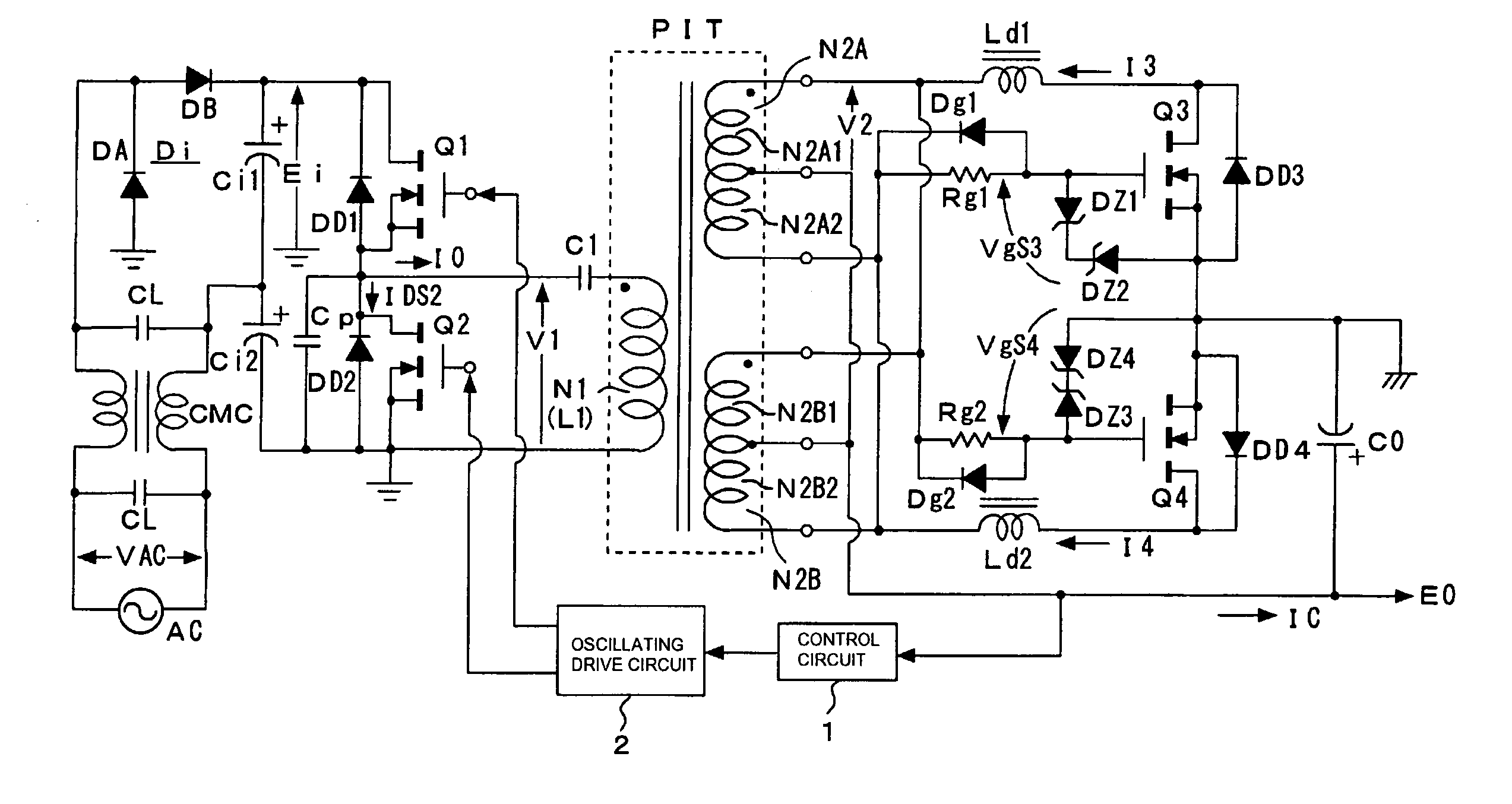
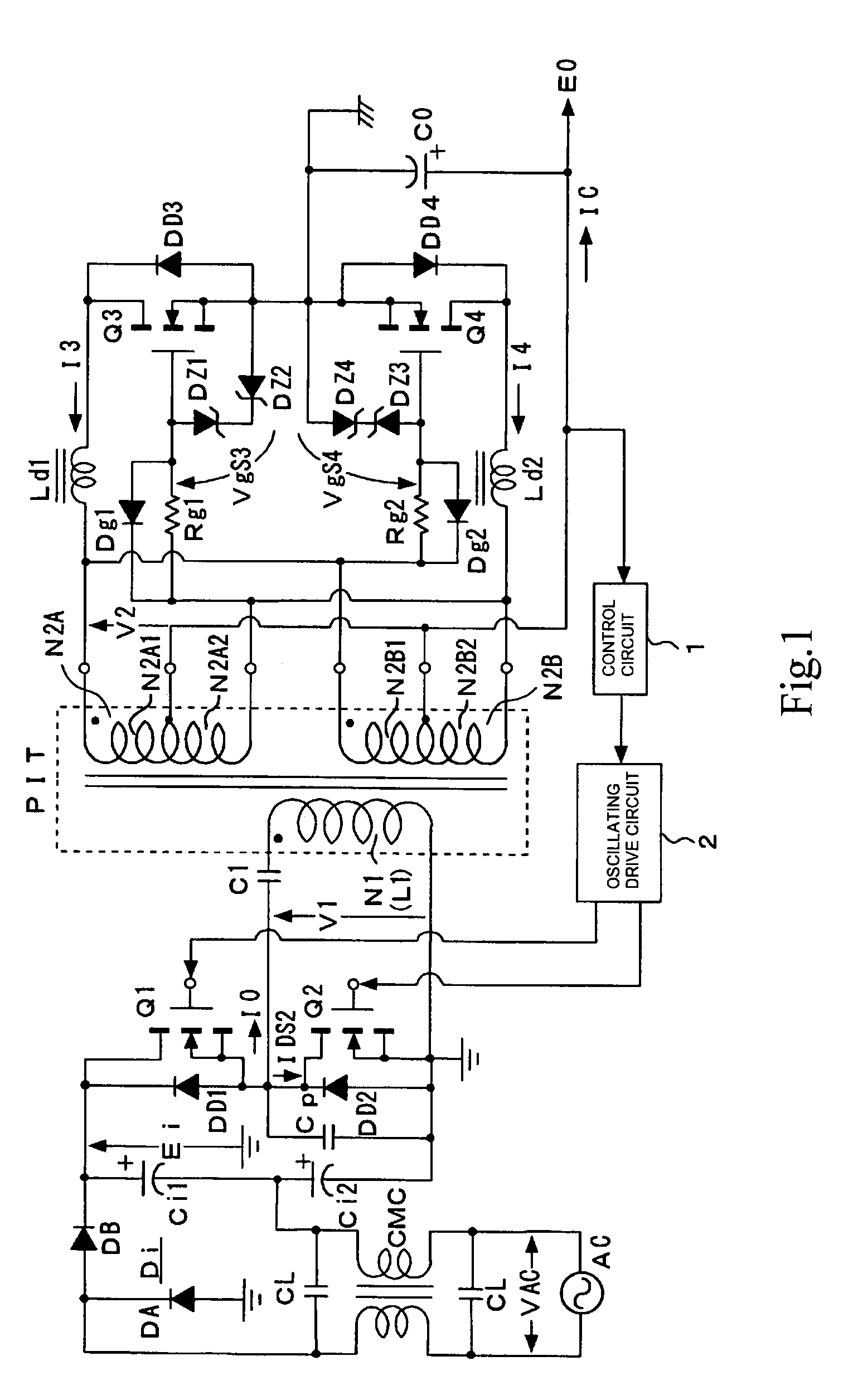
[0115]FIG. 1 shows a configuration example of a switching power circuit as the present invention. The power circuit shown in this figure adopts, as a basic configuration on the primary side, a configuration in which a partial voltage resonance circuit is combined with a current resonance type converter based on a separately excited type half-bridge coupling system.

[0116]In the power circuit shown in the figure, first, a noise filter composed of filter capacitors CL, CL and a common mode choke coil CMC is formed for a commercial AC power source AC.

[0117]On the latter stage next to the noise filter, a double voltage rectification circuit composed of a rectification circuit unit Di, which consists of rectifying diodes DA, DB, and two smoothing capacitors Ci1, Ci2 is provided, as shown in the figure. The double voltage rectification circuit produces a rectified and smoothed voltage Ei (DC input voltage) at a level corresponding to two times the AC input voltage VAC, as an end-to-end vol...

second embodiment

[0218]FIG. 8 shows a configuration example of a switching power circuit as the present invention. Incidentally, in FIG. 8, the portions which have been described above referring to FIG. 1 are denoted by the same symbols used above, and description thereof will be omitted.

[0219]The power circuit shown in this figure is characterized in that, in the power circuit in the first embodiment shown in FIG. 1 above, the center tap outputs of the secondary windings N2A, N2B are connected to the positive terminal of the smoothing capacitor C0 through an inductor L0, as shown in the figure.

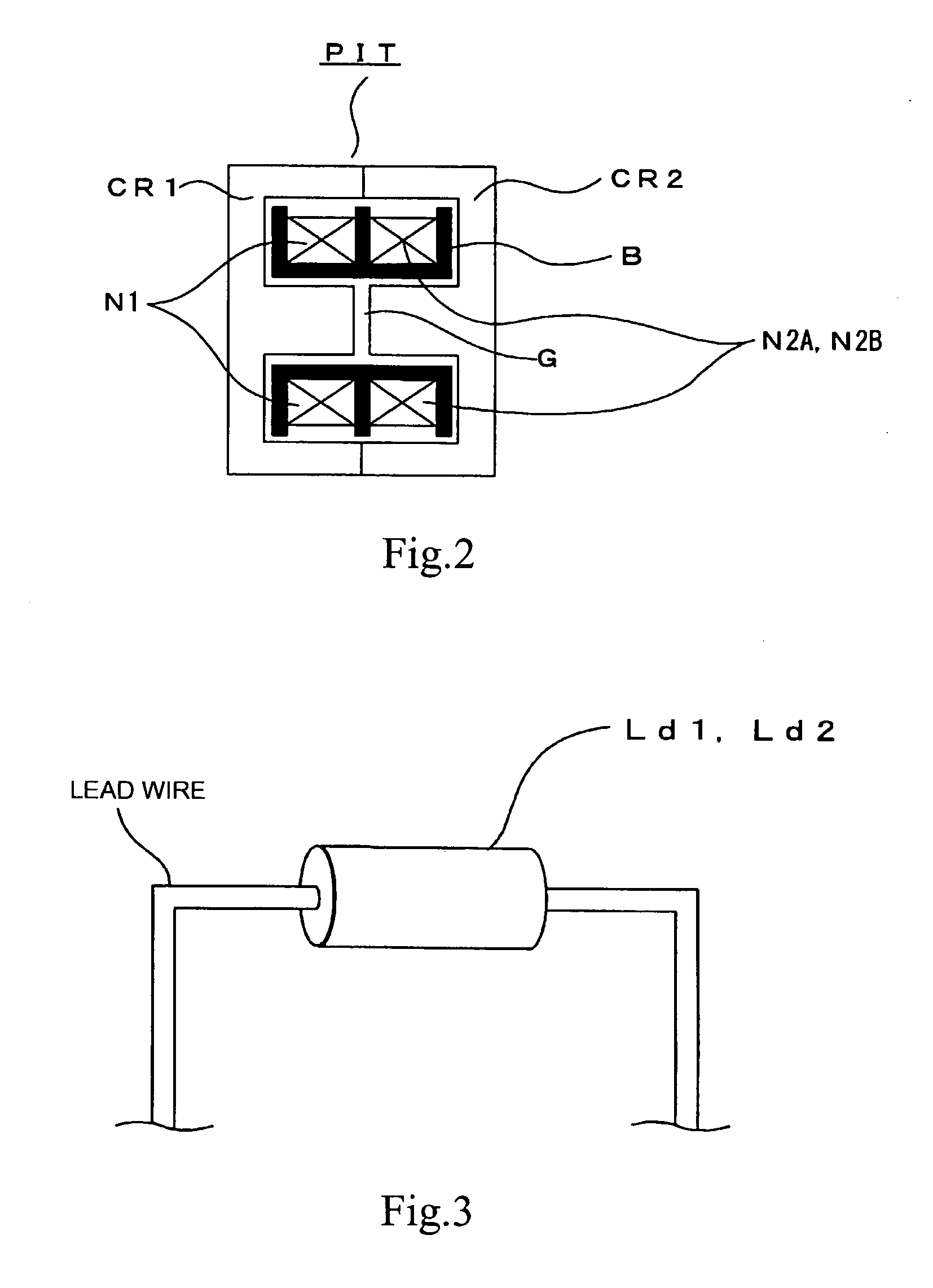
[0220]Besides, in the circuit of FIG. 8, the inductor L0 is inserted in common for the rectified current paths as above-mentioned; in this case, the inductor L0 is similarly set to have a low inductance of about 0.3 μH.

[0221]Therefore, the inductor L0 may also be configured as shown in FIGS. 4A and 4B above, to thereby obtain such a low inductance.

[0222]Operation waveforms of the power circuit shown in FIG. 8...

third embodiment

[0263]In the next place, the configuration of a switching power circuit as the present invention is shown in FIG. 10.

[0264]Incidentally, in FIG. 10, the portions which have been described referring to FIG. 1 above are denoted by the same symbols as used above, and description thereof will be omitted.

[0265]The switching power circuit according to the third embodiment is obtained by removing the inductors Ld1, Ld2 from the configuration of the power circuit according to the second embodiment shown in FIG. 8.

[0266]Only the inductor L0 is provided as the inductor inserted in the secondary-side rectified current path and, in addition, the inductance of the inductor L0 is set at 0.6 μH, which is higher than that in the case of FIG. 8.

[0267]FIG. 11 shows operation waveforms of individual components in the power circuit of the third embodiment.

[0268]With the inductor L0 having an inductance set to be higher than that in the case of FIG. 8, the secondary-side DC output voltage E0 in this cas...


PUM

PropertyMeasurementUnit
DC voltageaaaaaaaaaa
forward voltage dropaaaaaaaaaa
inductanceaaaaaaaaaa

Abstract

A switching power circuit in which a synchronous rectification circuit of the winding voltage detection system by use of a resistance device is provided on the secondary side of a compound resonance type converter, whereby a high power conversion efficiency can be obtained, and a reduction in the circuit scale through circuit simplification can be had. The gap length of an insulated converter transformer is enlarged to set the coupling coefficient at about 0.8, and the numbers of turns of the primary winding and the secondary windings are so set that the induced voltage level in the secondary winding is not more than 2 V / T. This causes the secondary-side rectified current to be in a continuous mode even under a heavy load condition by setting the magnetic flux density of the core in the insulated converted transformer to be not more than a predetermined value. Further, with inductors inserted into each rectified current circuit on the secondary side, the back electromotive forces in the inductors suppress a backward current generated in the rectified current, whereby a further reduction in the reactive power can be obtained.

Description

TECHNICAL FIELD[0001]The present invention relates to a switching power circuit provided as a power source in various electronic apparatuses.BACKGROUND ART [0002]As switching power circuits, those adopting a switching converter of, for example, a fly-back converter type, a forward converter type or the like are widely known. In these switching converters, the switching operation waveform is a rectangular waveform and, therefore, there is a limitation in suppressing the switching noises. In addition, due to their operation characteristics, it is known that there is also a limitation in enhancing the power conversion efficiency.[0003]In view of the foregoing, a variety of switching power circuits based on a resonance type converter have been proposed and put to practical use. The resonance type converter makes it possible to easily obtain a high power conversion efficiency, and to realize a low-noise property because the switching operation waveform is a sinusoidal waveform. Besides, ...

Claims


Application Information

Patent Timeline
Patent Type & Authority Patents(United States)
IPC IPC(8): H02M7/217H02M3/335H01F3/14H01F17/04H01F17/06H01F38/08H02M3/28
CPCH01F3/14H01F38/08H02M3/28H02M3/33592H01F17/043Y02B70/1475H01F2017/065Y02B70/10
Inventor YASUMURA, MASAYUKI
Owner SONY CORP
Why Eureka
Try Eureka