Very high energy, high stability gas discharge laser surface treatment system

a gas discharge laser and surface treatment technology, which is applied in the field of high power and high stability gas discharge lasers, can solve the problems of increasing costs, increasing costs, and consuming more power, and the gas discharge lasers known in the art are not available for providing an infinite spectrum of center wavelengths

Inactive Publication Date: 2007-01-23
CYMER INC
View PDF50 Cites 38 Cited by
  • Summary
  • Abstract
  • Description
  • Claims
  • Application Information

AI Technical Summary

Benefits of technology

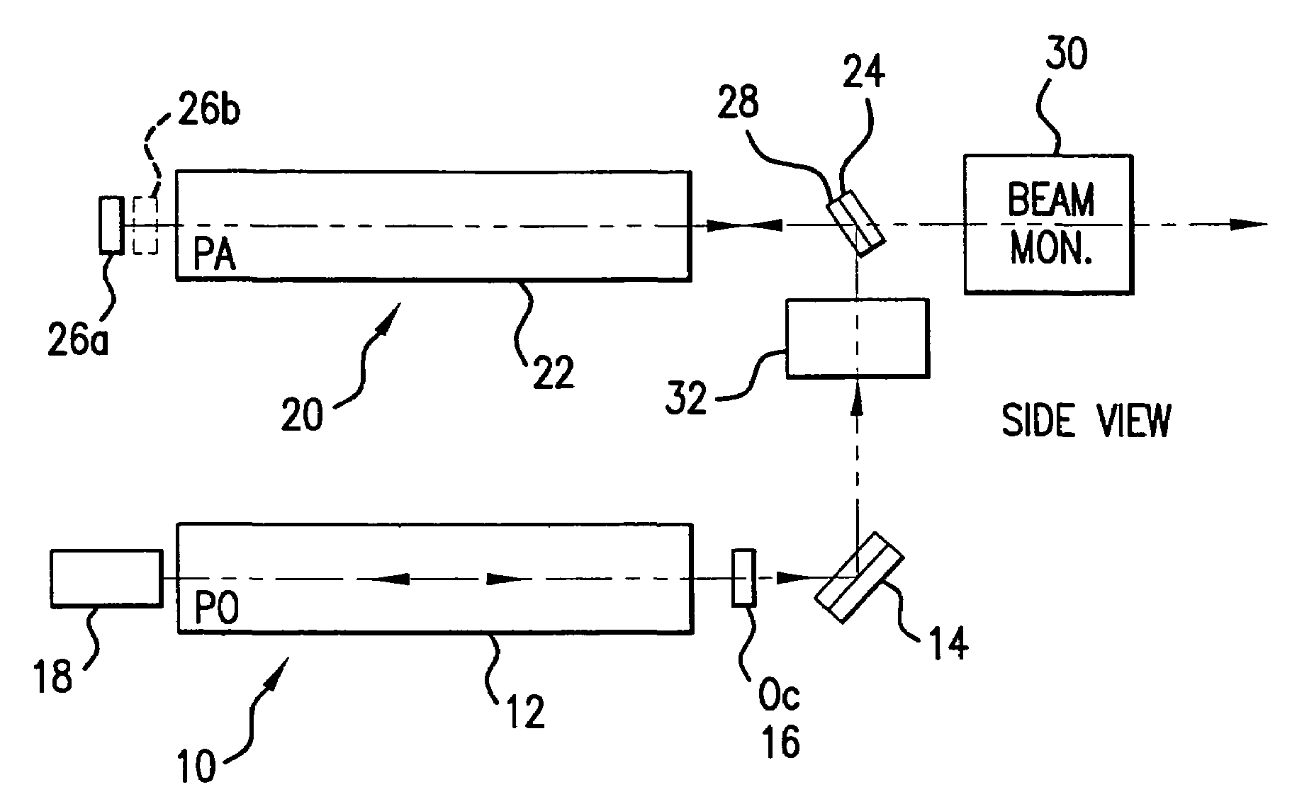
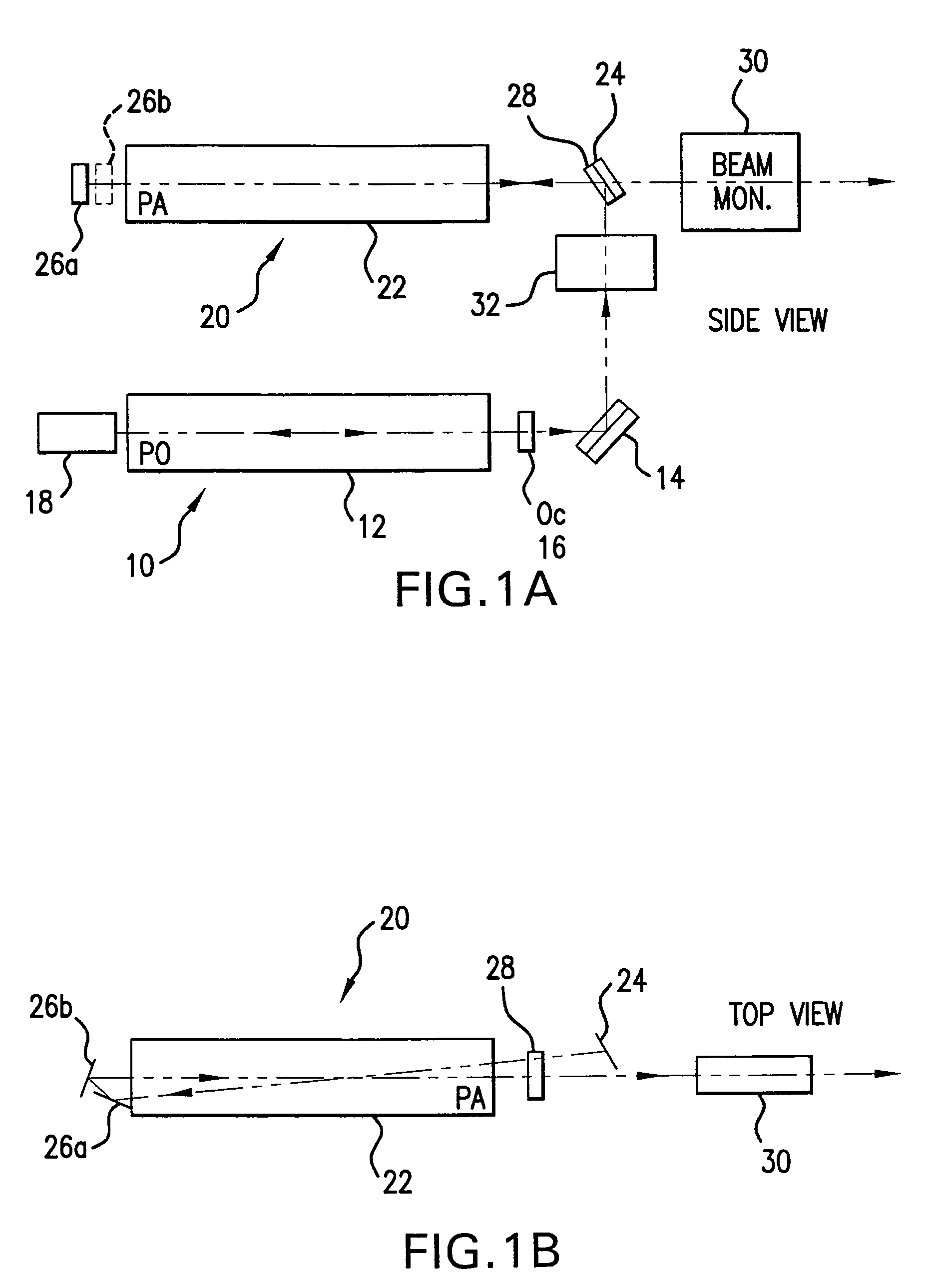
[0014]A gas discharge laser crystallization apparatus and method for performing a transformation of a crystal makeup or orientation in the substrate of a workpiece is disclosed which may comprise, a multichamber laser system comprising, a first laser unit comprising, a first and second gas discharge chamber; each with a pair of elongated spaced apart opposing electrodes contained within the chamber, forming an elongated gas discharge region; a laser gas contained within the chamber comprising a halogen and a noble gas selected to produce laser light at a center wavelength optimized to the crystallization process to be carried out on the workpiece; a power supply module comprising, a DC power source; a first and a second pulse compression and voltage step up circuit connected to the DC power source and connected to the respective electrodes, comprising a multistage fractional step up transformer having a plurality of primary windings connected in series and a single secondary winding passing through each of the plurality of primary windings, and a solid state trigger switch; and a laser timing and control module operativ

Problems solved by technology

Polycrystaline silicon (Poly-Si) TFT screens are brighter and more readable than, e.g., amorphous silicon (aSi) TFT LCD screens, but can consume more power and can be generally more expensive, in part due to currently available manufacturing techniques, an in particular, e.g., impacts on manufacturing yields due to certain limitations in the currently available manufacturing technologies.
Gas discharge lasers known in the art are not available for providing an infinite spectrum of center wavelengths due to the physical and chemical reactions taking

Method used


Image

  • Very high energy, high stability gas discharge laser surface treatment system
  • Very high energy, high stability gas discharge laser surface treatment system
  • Very high energy, high stability gas discharge laser surface treatment system

Examples


Embodiment Construction

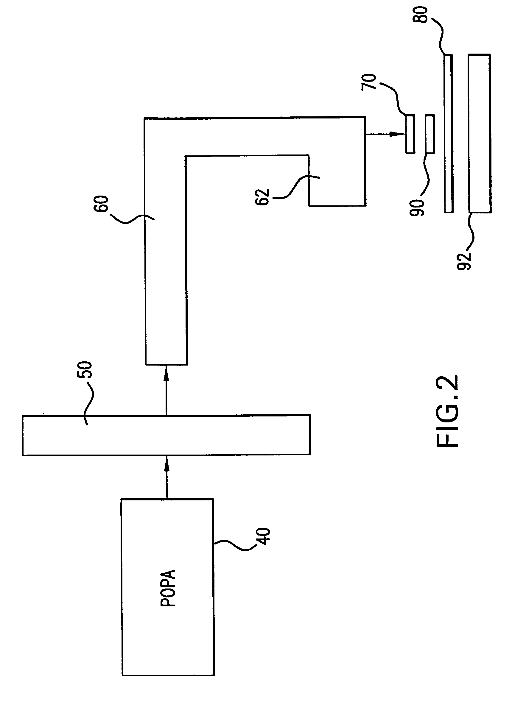
[0024]The present invention contemplates extending Applicants assignee's existing fluoride-based excimer technology to, e.g., XeCl lasers, e.g., for surface and material treatment applications. In particular, e.g., such a laser can be used to advance the capabilities of existing systems for large area annealing, e.g., of flat panel displays (TFT annealing), e.g., the Lambda-Physik XeCl laser (1 J, 300 Hz) noted above.

[0025]As contemplated by the present invention a high power, high energy XeCl laser is disclosed that can be optimized, e.g., for large area annealing, e.g., of 5th generation glass panels, e.g., for flat panel displays. Also provides according to the present invention is a high efficiency beam delivery unit that can, e.g., deliver constant fluence, e.g., in the form of an elongated slit, several hundred millimeters long and a fraction of a millimeter wide, e.g. 370 mm×0.4 mm.

[0026]Based on roadmaps for glass substrates, the substrate sizes would increase to 1250 mm×110...


PUM

PropertyMeasurementUnit
Timeaaaaaaaaaa
Temperatureaaaaaaaaaa

Abstract

A gas discharge laser crystallization apparatus and method for performing a transformation of a crystal makeup or orientation in the substrate of a workpiece is disclosed which may comprise, a multichamber laser system comprising, a first laser unit comprising, a first and second gas discharge chamber; each with a pair of elongated spaced apart opposing electrodes contained within the chamber, forming an elongated gas discharge region; a laser gas contained within the chamber comprising a halogen and a noble gas selected to produce laser light at a center wavelength optimized to the crystallization process to be earned out on the workpiece; a power supply module comprising, a DC power source; a first and a second pulse compression and voltage step up circuit connected to the DC power source and connected to the respective electrodes, comprising a multistage fractional step up transformer having a plurality of primary windings connected in series and a single secondary winding passing through each of the plurality of primary windings, and a solid state trigger switch; and a laser timing and control module operative to time the closing of the respective solid state switch based upon operating parameters of the respective first and second pulse compression and voltage step up circuit to effect operation of the first and second laser units as either a POPA configured laser system or a POPO configured laser system to produce a single output laser light pulse beam. As a POPA laser system relay optics may be operative to direct a first output laser light pulse beam from the first laser unit into the second gas discharge chamber; and, the timing and control module operates to create a gas discharge between the second pair of electrodes while the first output laser light pulse beam is transiting the second discharge region, within plus or minus 3 ns and as a POPO, combining optics combine the output beams, and timing creates pulse separation in the combined output a preselected time plus or minus 3 ns.

Description

RELATED APPLICATIONS[0001]This application is a continuation-in-part of U.S. application Ser. No. 10 / 722,992 entitled VERY HIGH ENERGY, HIGH STABILITY GAS DISCHAREGE LASER SURFACE TREATMENT SYSTEM, filed Nov. 26, 2003 now abandoned; of Ser. No. 10 / 631,349, entitled CONTROL SYSTEM FOR TWO CHAMBER GAS DISCHARGE LASER, filed Jul. 30, 2003 now U.S. Pat. No. 7,039,086; of Ser. No. 10 / 233,253, entitled LITHOGRAPHY LASER WITH BEAM DELIVERY AND BEAM POINTING CONTROL, filed on Aug. 30, 2002 now U.S. Pat. No. 6,704,339; of Ser. No. 10 / 012,002, now U.S. Pat. No. 6,625,191, filed on Nov. 30, 2001, entitled VERY NARROW BAND, TWO CHAMBER, HIGH REP RATE GAS DISCHARGE LASER SYSTEM, with inventors Knowles, et al., published on Oct. 24, 2002, Pub. No. US20020154668A1; Ser. No. 09 / 943,343, now U.S. Pat. No. 6,567,450, filed on Aug. 29, 2001, entitled VERY NARROW BAND, TWO CHAMBER, HIGH REP RATE GAS DISCHARGE LASER SYSTEM, with inventors Myers et al., published on Apr. 18, 2002, Pub. No. US20020044586A...

Claims


Application Information

Patent Timeline
IPC IPC(8): H01S3/22H01S3/03H01S3/00H01S3/036H01S3/038H01S3/041H01S3/0975H01S3/134H01S3/139H01S3/225H01S3/23
CPCH01S3/005H01S3/036H01S3/0385H01S3/225H01S3/2366H01S3/038H01S3/041H01S3/0975H01S3/134H01S3/139H01S3/22H01S3/2207H01S3/2251H01S3/2256H01S3/2258H01S3/2333H01S3/0057H01S3/09702H01S2301/08H01S3/2383
Inventor DAS, PALASH P.BOLLIGER, BRUCE E.PATEL, PARTIV S.KLENE, BRIAN C.MELCHER, PAUL C.SAETHRE, ROBERT B.
Owner CYMER INC
Why Eureka
Try Eureka