Mask inspection method, mask defect inspection system, and method of production of mask

a mask and defect technology, applied in the field of mask inspection methods, mask defect inspection systems, and mask production methods, can solve the problems of reducing the amount of light passing through the mask, unable to obtain sufficient contrast, and affecting the production efficiency of masks, so as to improve the efficiency of mask production, reduce the number of repaired defects, and improve the effect of mask production

Inactive Publication Date: 2007-01-23
SONY CORP
View PDF16 Cites 3 Cited by
  • Summary
  • Abstract
  • Description
  • Claims
  • Application Information

AI Technical Summary

Benefits of technology

[0020]Due to this, only defects substantially affecting transfer are repaired, and the time required for repairing defects not substantially affecting transfer becomes unnecessary. Therefore, the throughput of mask production is improved. Also, when comparing with a case of detecting defects using a flat acceptable defect size, the number of repaired defects can be reduced and accurate repair of detects becomes possible. Therefore, the yield of mask production is improved.

Problems solved by technology

However, compared with when miniaturizing patterns by shortening the exposure wavelength, in general, in super-resolution techniques, line width errors, defects, etc. on the mask have a greater effect on the transfer patterns.
Further, when forming a dense pattern on the phase shift mask, the amount of the light passing through the mask decreases and sufficient contrast cannot be obtained, so the effect of defects becomes greater.
The use of super-resolution techniques however increases the difference between the effects of dense and sparse patterns.
Conversely, there is a possibility of defect which actually have no effect on transfer not being allowed in sparse portions of a pattern.
Therefore, with the conventional method of detection of defects based on a flat acceptable defect size, it becomes difficult to determine defects.
Generally, the smaller the defect, the more difficult it is to repair the defect with a high accuracy.
Therefore, when setting a flat acceptable defect size, if the acceptable defect size is made smaller and the number of defects increases, the time required for precise repair of all the defects becomes longer.
If trying to shorten the time required for repairing defects, the problem arises of a drop in the probability of repair of defects at a defect repair system.

Method used


Image

  • Mask inspection method, mask defect inspection system, and method of production of mask
  • Mask inspection method, mask defect inspection system, and method of production of mask
  • Mask inspection method, mask defect inspection system, and method of production of mask

Examples


Embodiment Construction

[0036]Below, preferred embodiments of the mask inspection method, mask defect inspection system, and mask production method of the present invention will be described with reference to the accompanying drawings. The present invention can be applied to inspection of a mask used for photolithography employing super-resolution techniques. Here, the super-resolution techniques include the techniques of the exposure system side (modified illumination) or mask side (phase shift masks) or both combined.

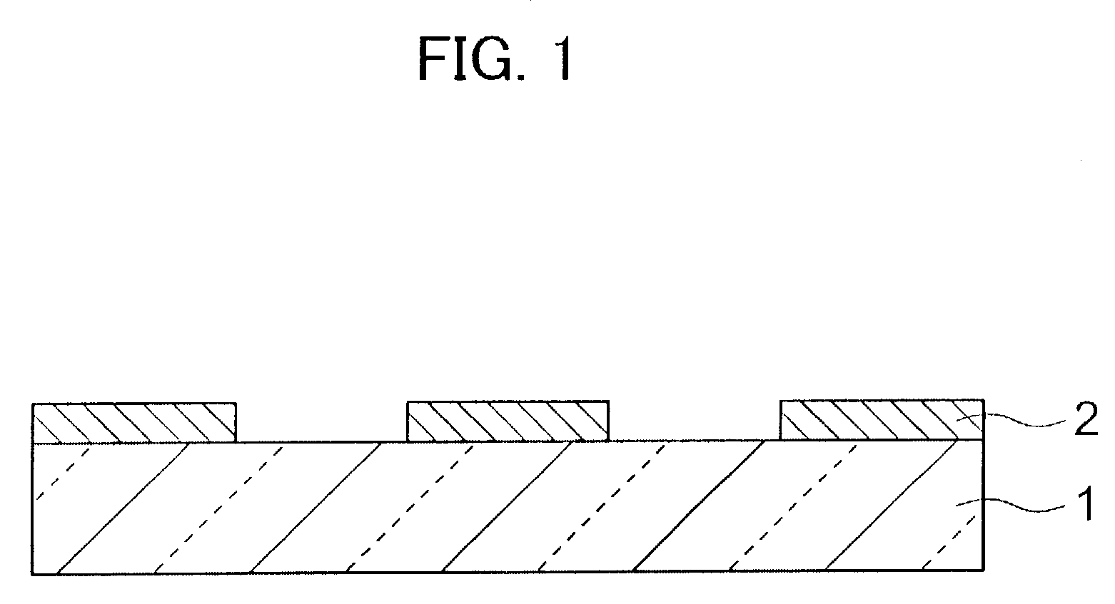
[0037]FIG. 1 is a cross-sectional view of an example of a photomask to which the mask inspection and production methods of the present invention are applied. As shown in FIG. 1, a predetermined pattern of light-blocking regions is formed by a light-blocking film 2 on a glass substrate 1. Non-light-blocking regions are not formed with the light-blocking film 2. A binary mask is a mask wherein the light-blocking film 2 does not pass any light. Modified illumination is used as the super-resolut...


PUM

PropertyMeasurementUnit
sizeaaaaaaaaaa
sizeaaaaaaaaaa
widthaaaaaaaaaa

Abstract

A method of inspection for detecting pattern defects in a mask used for transferring a predetermined pattern of regions passing and blocking an exposure beam, comprising the steps of presetting different acceptable defect sizes for a plurality of conditions different in the line and/or space of the pattern, detecting a defect and recognizing the line and space of the pattern at the defect part, selecting an acceptable defect size corresponding to the line and space of the pattern recognized at the defect part and comparing it with the size of the detected defect, and determining a defect larger than the acceptable defect size as a defect requiring repair; a mask defect inspection system for inspection according to the method, and a mask production method including a step of the inspection.

Description

BACKGROUND OF THE INVENTION[0001]1. Field of the Invention[0002]The present invention relates to methods of inspection and production of a mask used in a lithography step in production of a semiconductor device etc. and to a mask defect inspection system.[0003]2. Description of the Related Art[0004]Along with the miniaturization of semiconductor devices, the pattern size on a photomask used for photolithography has become increasingly smaller. Up to now, in photolithography, accuracy of formation of fine patterns has been improved by shortening the exposure wavelength. However, in recent years, transfer patterns have become shorter than the exposure wavelength, so super-resolution techniques have been broadly used to extend the life of photomasks at the same exposure wavelength.[0005]Super-resolution techniques are roughly classified into two types: ones conducted at an exposure system (stepper or scanner) side and ones conducted on a mask side. The former techniques are called “mod...

Claims


Application Information

Patent Timeline
Patent Type & Authority Patents(United States)
IPC IPC(8): G06K9/00G01N21/956G03F1/84G06T1/00G06T7/00
CPCG03F1/84G06T7/0006G06T2207/30148
Inventor ISHIKAWA, KIICHI
Owner SONY CORP
Why Eureka
Try Eureka