Frequency agile tuner and variable rate decimator for digital demodulator

a digital demodulator and variable rate technology, applied in the field of digital signal processing, can solve the problems of speed and quality of signal demodulation that are not optimized, and achieve the effect of increasing the speed of operation

Inactive Publication Date: 2007-01-30
REMEC BROADBAND WIRELESS NETWORKS LLC
View PDF9 Cites 22 Cited by
  • Summary
  • Abstract
  • Description
  • Claims
  • Application Information

AI Technical Summary

Benefits of technology

[0013]In one embodiment, the apparatus of the present invention further includes a plurality of pipeline registers. In one embodiment of the present invention, each pipeline register is located between at least two consecutive sections of the M-section cascaded comb filter. Each pipeline register is configured to perform a pipeline computation on a plurality of input symbols in order to increase the speed of operation of each section of the M-section cascaded comb filter by N-factor by minimizing the combinatorial delay of N samples. A pipeline delay of the CIC Decimator having the plurality of pipeline registers is determined by one section of the M-section cascaded comb filter, wherein each section of the M-section cascaded comb filter includes the integer N registers.

Problems solved by technology

However, if each digital modem utilizes different sample clock signals, the modem architecture involves complicated analog components, and the speed and quality of signal demodulation is not optimized.

Method used


Image

  • Frequency agile tuner and variable rate decimator for digital demodulator
  • Frequency agile tuner and variable rate decimator for digital demodulator
  • Frequency agile tuner and variable rate decimator for digital demodulator

Examples


example i

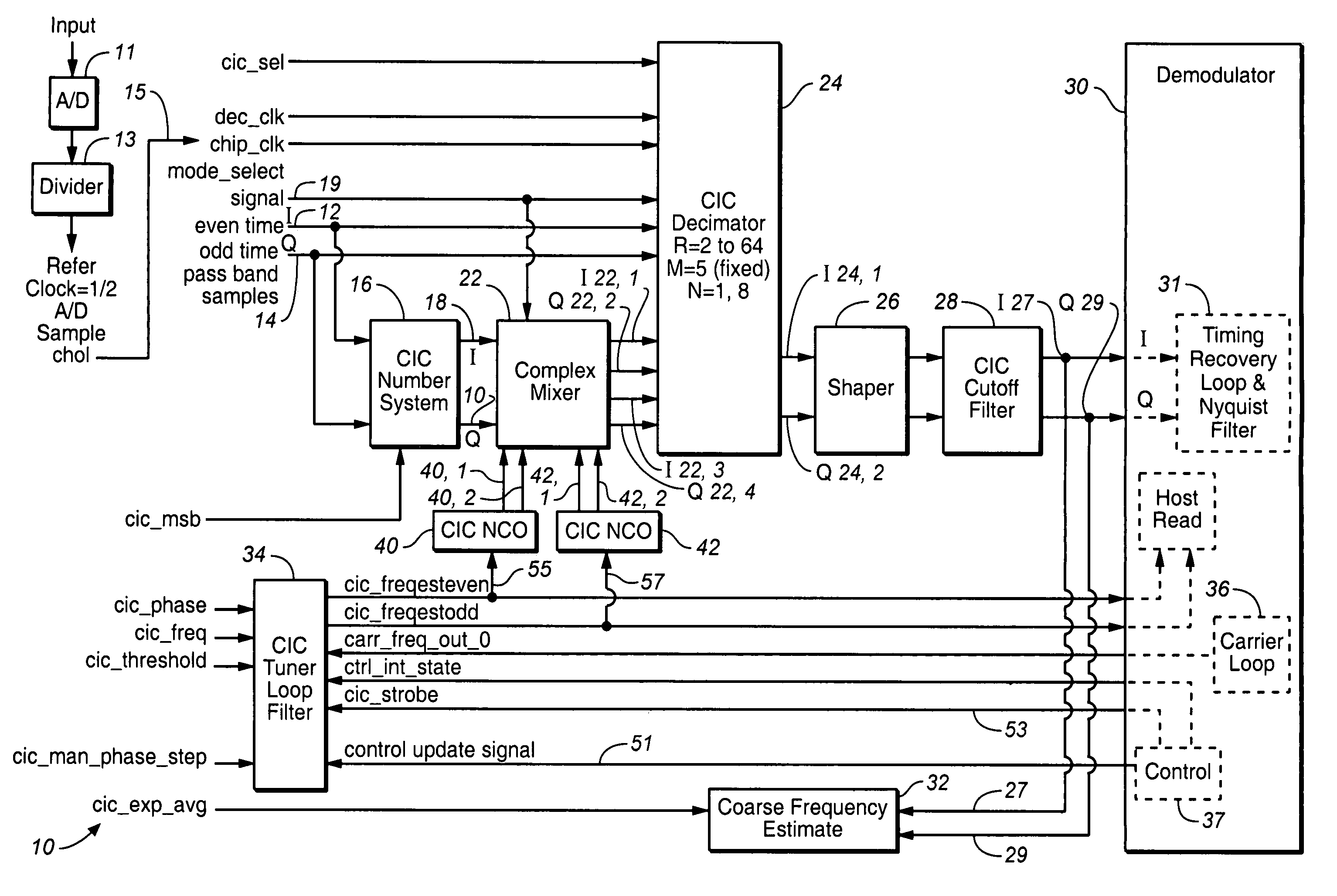
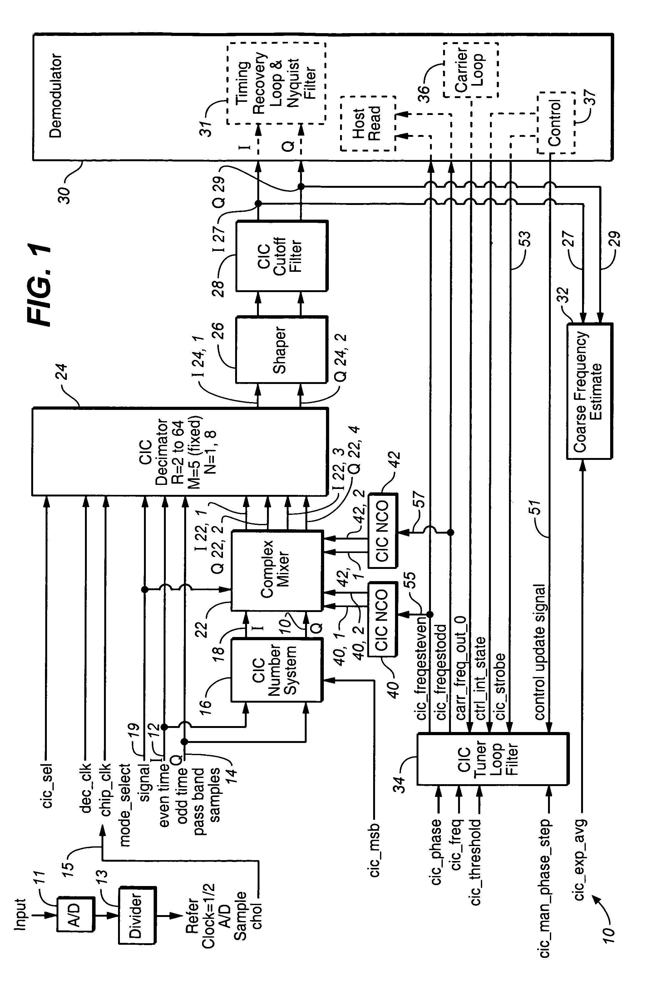
[0082]The number of bits in the comb filter section and in the integrator section (accumulator and register) has to be larger than the bit size of the input signal by the number of bits due to the gain growth factor equal to log2 [(RN)]M. For R=2, N=2, M=8, we have the gain growth factor equal to log2 [(4)]8 =16 bits. So, starting with the input signal including 12 bits, one has to store at least 28 bits in the accumulator register of the CIC Decimator filter of the present invention. As it is well known to those skilled in the art, this can be easily achieved.

[0083]Referring still to FIG. 1, in the passband mode of the present invention selected by using the mode_select signal 19, preferably, the A / D sample rate in the chip should be ultimately equal to ½ A / D rate, so that the minimum decimation rate Rmin is equal to 2.

example ii

[0084]The chip clock rate limits the maximum baud rate that can be processed. For chip clock rate equal to 100 MHz, the maximum baud rate is equal to ½ chip clock=50 MHz, because the chip needs to have at least 2 samples per symbol the way the demodulator of the present invention is set up. The number of parallel sections K in the CIC K-stage integrator is equal to A / D rate divided by the chip clock rate. For A / D sample rate 800 MHz, and K=8, the chip can process 8 samples per chip clock. As the incoming signal spectrum is sampled faster, less complicated analog designs are required. The downside to the present circuit implementation is that the complexity of the circuit is transferred to the digital part of the circuit. However, the gain imbalances, quadrature imbalances, and DC offsets present in analog baseband circuits are on the order of (−30) dB in the best case scenario, whereas the compensation techniques employed in digital demodulators can reduce theses errors to a level o...


PUM


Abstract

An apparatus for demodulating a digital input signal having a pre-assigned symbol rate by using a single sample clock signal is disclosed. The pre-assigned symbol rate is selected from the group consisting of a plurality of symbol rates. The apparatus comprises: a Cascaded Integrated Comb (CIC) Decimator filter configured to perform a filtering-decimation operation to isolate the down converted digital signal having the pre-assigned symbol rate; a Shaper configured to restore an original spectrum of the I and Q components of the CIC output signal; and a CIC tuner loop filter configured to insert the estimated by the Coarse Frequency estimation block frequency offset into a carrier loop in order to complete a carrier recovery of the pre-assigned input digital signal.

Description

BACKGROUND OF THE INVENTION[0001]1. Field of the Invention[0002]The present invention relates to the filed of the digital signal processing, and more specifically, to the field of digital demodulators.[0003]2. Discussion of the Prior Art[0004]When a plurality of symbol rates are used by transceivers of digital signals, each transceiver should be capable of multi-rate operations with different symbols rates. However, if each digital modem utilizes different sample clock signals, the modem architecture involves complicated analog components, and the speed and quality of signal demodulation is not optimized.[0005]What is needed is to design a digital modem that allows multi-rate operations with different symbol rates, but that utilizes a single sample clock signal, thus reducing the complexity of analog components and increasing the speed of signal acquisition.SUMMARY OF THE INVENTION[0006]To address the shortcomings of the available art, the present invention provides for a digital mo...

Claims


Application Information

Patent Timeline
Patent Type & Authority Patents(United States)
IPC IPC(8): H04L27/06H04B1/18
CPCH03H17/0664H03H17/0671H04L27/2273H04L27/3827H04L25/03828H03H2220/04H04L7/0029H04L7/0054H04L2027/0069H04L2027/003H04L2027/0057
Inventor FONG, MARKISAKSEN, DAVID BRUCE
Owner REMEC BROADBAND WIRELESS NETWORKS LLC
Why Eureka
Try Eureka