

X-ray microscope capillary condenser system
- Summary
- Abstract
- Description
- Claims
- Application Information
AI Technical Summary
Benefits of technology
Problems solved by technology
Method used
Image

Examples
Embodiment Construction
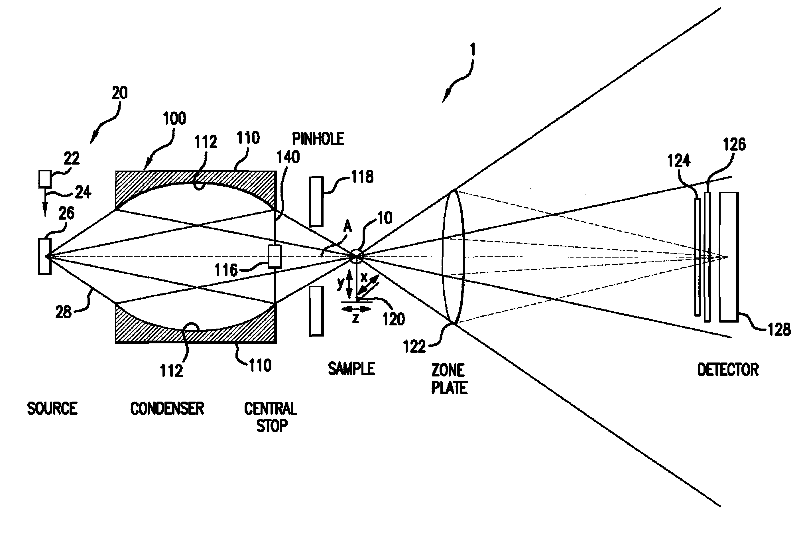
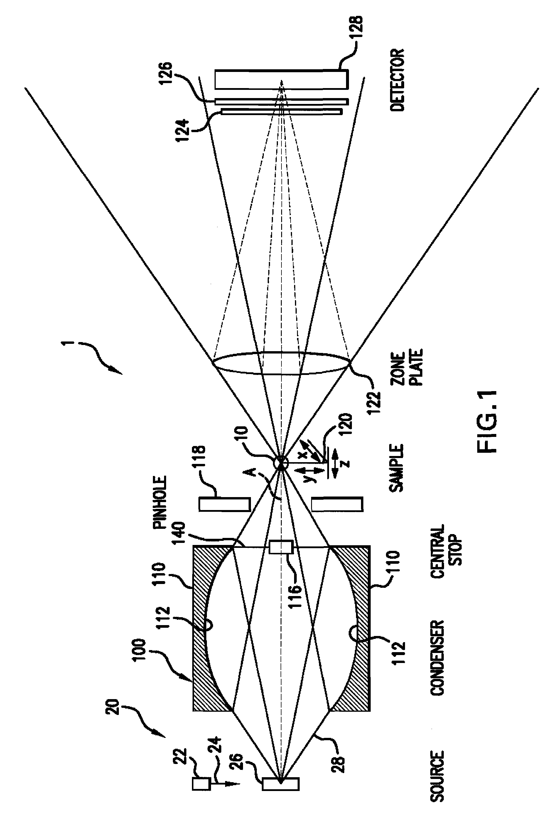
[0023]FIG. 1 is a schematic diagram of an X-ray microscope 1 using a capillary condenser system 100, which has been constructed according to the principles of the present invention.
[0024]Specifically, in the current embodiment, an electron bombardment laboratory X-ray source 20 is used. These systems comprise an electron gun 22 that generates an electron beam 24 that is directed at a target 26. Typically, the target 26 is selected from the group of: chromium, tungsten, platinum, or gold.
[0025]This bombardment of the target 26 generates X-ray radiation 28 by the process of x-ray fluorescence. The radiation is emitted, typically at a 6–45 degree, take-off angle.
[0026]These laboratory sources, however, produce a relatively weak radiation beam as compared to stronger sources, such as synchrotrons. As a result, the condenser system 100 is required. According to the invention, a capillary tube-based system is used.
[0027]Specifically, the capillary tube 110 is preferably made out of a glas...
PUM
 Abstract
Description
Claims
Application Information