Electrical contacts having solder stops

a technology of solder stops and electrical contacts, which is applied in the direction of sustainable manufacturing/processing, coupling device connection, and final product manufacturing, etc. it can solve the problems of reduced electrical performance of electrical connections between, reduced integrity of mechanical connections between electrical contacts and printed circuit boards, and reduced solder volume, so as to prevent solder wicking and prevent solder wicking. , the effect of preventing the wicking of solder

a technology of solder stops and electrical contacts, which is applied in the direction of sustainable manufacturing/processing, coupling device connection, and final product manufacturing, etc. it can solve the problems of reduced electrical performance of electrical connections between, reduced integrity of mechanical connections between electrical contacts and printed circuit boards, and reduced solder volume, so as to prevent solder wicking and prevent solder wicking. , the effect of preventing the wicking of solder

US7172438B2Active Publication Date: 2007-02-06SAMTEC

Image

  • Electrical contacts having solder stops
  • Electrical contacts having solder stops
  • Electrical contacts having solder stops

Examples


Embodiment Construction

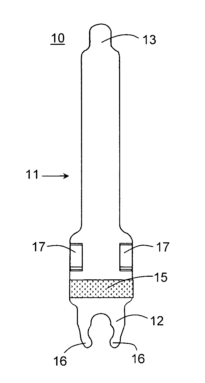
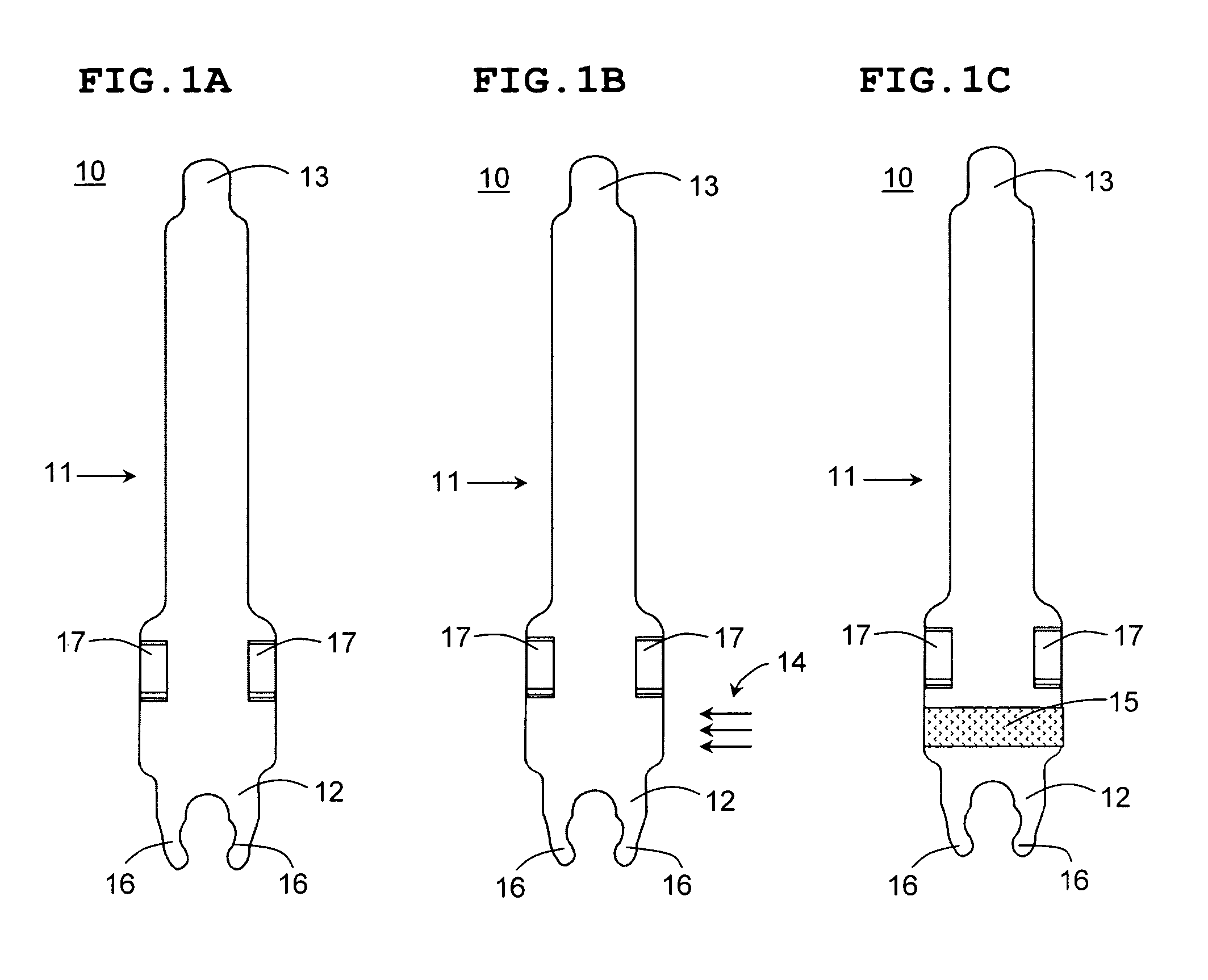
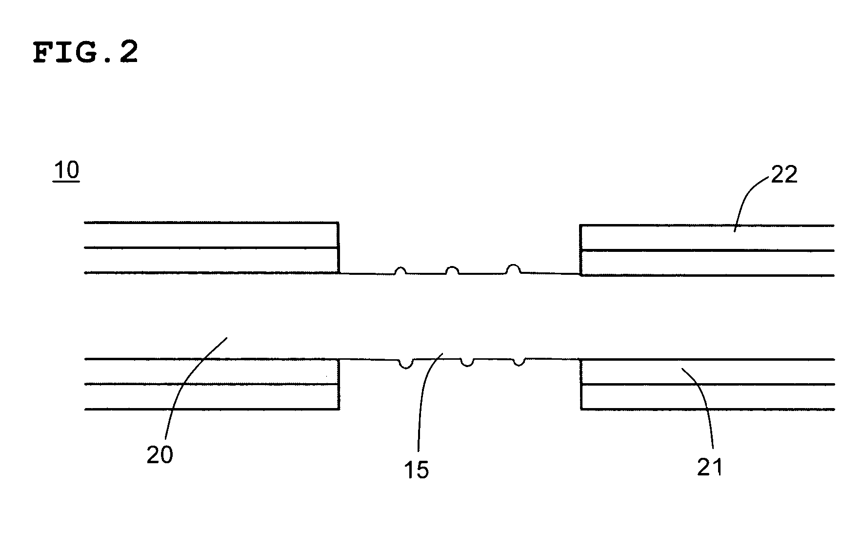
[0053]FIGS. 1A–1C illustrate a method of manufacturing, according to a first preferred embodiment of the present invention, an electrical contact 10 according to a second preferred embodiment of the present invention. FIG. 2 illustrates a close-up sectional view of an anti-wicking region 15 of the electrical contact 10.

[0054]FIG. 1A illustrates the electrical contact 10 having a contact body 11. The contact body 11 includes a contact tail 12 and a contact head 13. As shown in FIG. 1A, the contact tail 12 includes arms 16 for holding a fusible material, such as solder or a solder member (not shown). However, other arrangements for attaching solder to the contact tail 12 could also be used for attaching the fusible material in the form of, for example, solder balls or solder charges. Further, the contact tail 12 need not include any arrangement for holding solder. Instead, the fusible material or solder could be provided on any substrate to which the electrical contact 10 is to be sol...


PUM


Abstract

An electrical contact for use in an electrical connector, includes a contact body made of metal and having a contact head, a contact tail, and an anti-wicking region disposed between the contact head and the contact tail arranged to prevent wicking of a fusible material past the anti-wicking region in a direction toward the contact head. The anti-wicking region is defined by one of a laser-ablated portion, a laser marking material, a UV marking material, and an ink that is permanently disposed on the contact body.

Description

BACKGROUND OF THE INVENTION[0001]1. Field of the Invention[0002]The present invention relates to solder stops. More specifically, the present invention relates to solder stops on electrical contacts and to methods of making electrical contacts having solder stops.[0003]2. Description of the Related Art[0004]As shown in FIG. 6, it is well known in the art to use solder 64 to form an electrical connection between a connection pad 65 on a printed circuit board 66 and the contact tail 63 of an electrical contact 60. When the solder 64 is reflowed to join the contact tail 63 of the electrical contact 60 to the connection pad 65 on the printed circuit board 66, the solder 64 will wick up the length of the contact body 61, which reduces the amount of solder 64 located between the contact tail 63 of the electrical contact 60 and connection pad 65 on the printed circuit board 66.[0005]The reduction in the amount of solder has the following disadvantageous effects: (a) causes a reduction in t...

Claims


Application Information

Patent Timeline
06 Feb 2007
Publication
US7172438B2
IPC
H01R12/00
CPC
H01R12/57; H01R13/02; H01R43/00; H05K3/3426; H01R13/03; H01R13/41; H01R12/707; H05K2201/10909
Inventors
VICICH, BRIAN; KOOPMAN, STEVE