Patterned coating method employing polymeric coatings

a technology of polymeric coatings and patterned coatings, applied in the direction of resistive material coatings, circuit masks, packaging, etc., can solve the problems of difficult to meet the needs of photoimaging, difficult to remove solvents, and difficult to apply and remove tapes

Active Publication Date: 2007-02-13
3M INNOVATIVE PROPERTIES CO
View PDF32 Cites 25 Cited by
  • Summary
  • Abstract
  • Description
  • Claims
  • Application Information

AI Technical Summary

Problems solved by technology

However, coating build-up or edge distortion sometimes occurs near the pattern boundaries, and applying and removing the tape can be tedious.
The choice of suitable photoimaging r

Method used


Image

  • Patterned coating method employing polymeric coatings
  • Patterned coating method employing polymeric coatings
  • Patterned coating method employing polymeric coatings

Examples


example 1

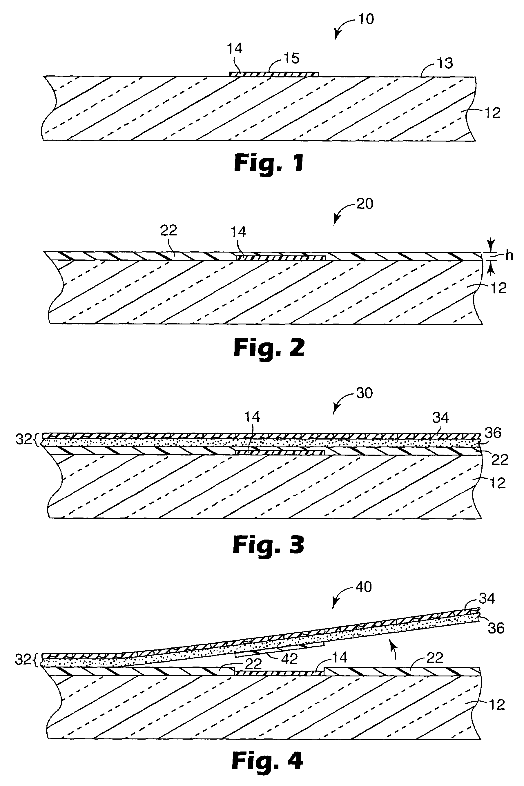
[0044]Using a hand-held cotton swab, generally C-shaped and generally straight streaks of FLUORAD™ FC-722 fluoroaliphatic copolymer coating (formerly commercially available from Dyneon LLC Oakdale, Minn.) were formed on the surface of a 50 mm×75 glass slide. A rapid application rate was employed in order to obtain a release polymer coating thickness of about 0.1 μm as measured using a TENCOR™ profilometer (commercially available from KLA-Tencor Corporation, San Jose, Calif.). FIG. 7 shows the profilometer scan. In cross-section the release polymer coating looked like coating 14 in FIG. 1.

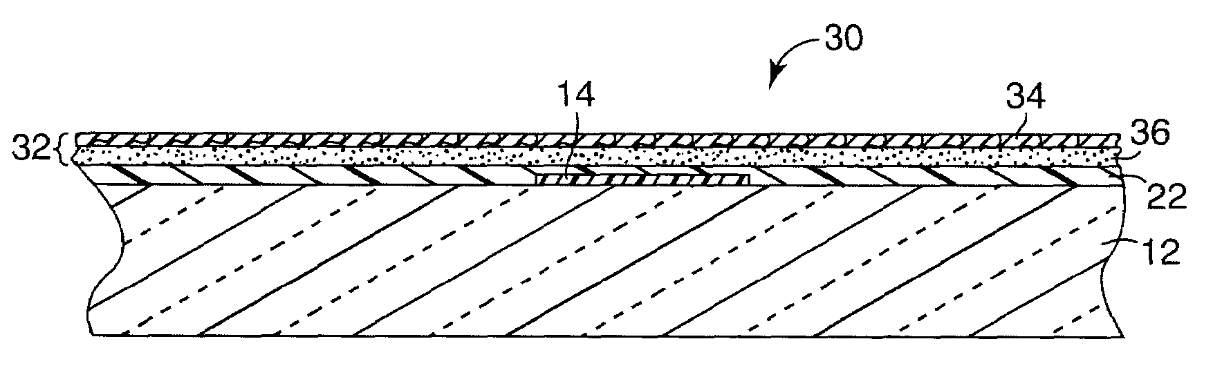
[0045]Using a spin-coating apparatus operated at 6000 rpm, No. PI 2579B polyimide (commercially available from HD Microsystems LLC, Parlin, N.J.) was coated over the pattern and over the remainder of the substrate to form a substrate-adherent polymer coating having a substantially constant height of about 0.3 μm with respect to the substrate. In cross-section the resulting article looked like articl...

example 2

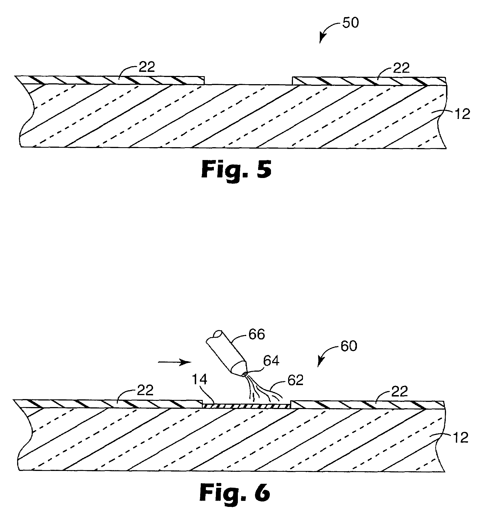
[0047]Using the general method of Example 1, a fluoropolymer release polymer pattern was formed on a glass slide. The release polymer was overcoated with a solvent-based ink applied by dip coating to form a 0.5 μm thick substrate-adherent polymer coating. A portion of the substrate-adherent polymer was removed using tape, and the underlying release polymer was removed using HFE-7200 hydrofluoroether. FIG. 10 and FIG. 11 show profilometer scans of the patterned article before and after removal of the release polymer. As shown in FIG. 10 and FIG. 11, the substrate-adherent polymer edges were sharply defined with the major exposed portion of each sidewall being generally perpendicular to the substrate.


PUM

PropertyMeasurementUnit
Heightaaaaaaaaaa
Heightaaaaaaaaaa
Heightaaaaaaaaaa

Abstract

Patterned articles can be prepared by applying a release polymer to a substrate in a desired pattern, applying a substrate-adherent polymer over the pattern and substrate, and mechanically removing the substrate-adherent polymer from the pattern without requiring solvent. Suitable mechanical removal methods include applying adhesive tape to the substrate-adherent polymer and peeling the tape and substrate-adherent polymer away from the pattern, and abrading the substrate-adherent polymer from the pattern using impact media.

Description

FIELD OF THE INVENTION[0001]This invention relates to methods for forming patterned coatings.BACKGROUND[0002]In many applications, especially those involving electronics, patterned coatings must be formed in one or more layers on a substrate. Available pattern formation methods include masking the substrate with tape and photoimaging. In masking, a tape is applied in a pattern over parts of the substrate. After coating the substrate using any convenient method (e.g., spin coating) and drying or curing the coating, the tape can be manually removed, leaving the patterned coating. However, coating build-up or edge distortion sometimes occurs near the pattern boundaries, and applying and removing the tape can be tedious. In photoimaging, a photocurable polymer is applied to the substrate, imaged in a pattern (using, for example a partially transparent and partially occluded mask and UV or shorter wavelength light), then removed from the unimaged areas (in a step sometimes called “lift-o...

Claims


Application Information

Patent Timeline
IPC IPC(8): B05D1/32B05D5/12B41M3/00B41M5/00B41M7/00H05K3/00
CPCB41M5/0058B41M5/0064B41M5/007H05K3/0079B41M5/0047B41M1/12B41M1/28B41M1/30B41M1/34B41M3/003B41M3/006H05K2203/0582H05K2203/025H05K2203/0264B41M3/00B41M5/00B41M7/00H05K3/00
Inventor FREE, M. BENTONPEKUROVSKY, MIKHAIL L.
Owner 3M INNOVATIVE PROPERTIES CO
Why Eureka
Try Eureka