Method for plasma formation for extreme ultraviolet lithography-theta pinch

a technology of ultra-violet lithography and plasma formation, which is applied in the field of ultra-violet lithography, can solve the problems of high cost of lasers of sufficient power, low efficiency and short life, and is difficult to achieve the effect of improving the efficiency of lasers

Inactive Publication Date: 2007-02-20
THE UNITED STATES AS REPRESENTED BY THE DEPARTMENT OF ENERGY
View PDF2 Cites 53 Cited by
  • Summary
  • Abstract
  • Description
  • Claims
  • Application Information

AI Technical Summary

Benefits of technology

[0008]An object of this invention is to provide a method and apparatus for generating electromagnetic radiation in the range of 13.5 nm that does not degrade or erode the electrode material. An additional objection of this invention is to provide a method and apparatus which eliminates the need for an electrode in the light generation process.

Problems solved by technology

The problem with creating the plasma with a laser is that lasers of sufficient power are expensive, both to purchase and to operate.
However, these devices are limited in repetition rate due to large per pulse electrical energy requirements, and short lived internal components.
Further, the problem with electrodes, in the plasma environment, is that electrodes, particularly the anode, suffer from a high erosion rate due to particle and heat fluxes resulting in low efficiency and short lifetimes.
One of the main obstacles now in achieving EUVL commercial goals in discharge produced plasma (Hereinafter referred to as “DPP”) devices is electrode erosion at the required high power necessary for high volume manufacturing (Hereinafter referred to as “HVM”).
However, these facilities were never intended for use as powerful machines operating at high frequency.
If the plasma-facing component (PFC) surface has an area less 100 cm2 the heat load onto surface exceeds 1 kW / cm2 which is difficult to remove by conventional methods as it is well studied in fusion reactor and space research investigations.

Method used


Image

  • Method for plasma formation for extreme ultraviolet lithography-theta pinch
  • Method for plasma formation for extreme ultraviolet lithography-theta pinch
  • Method for plasma formation for extreme ultraviolet lithography-theta pinch

Examples


Embodiment Construction
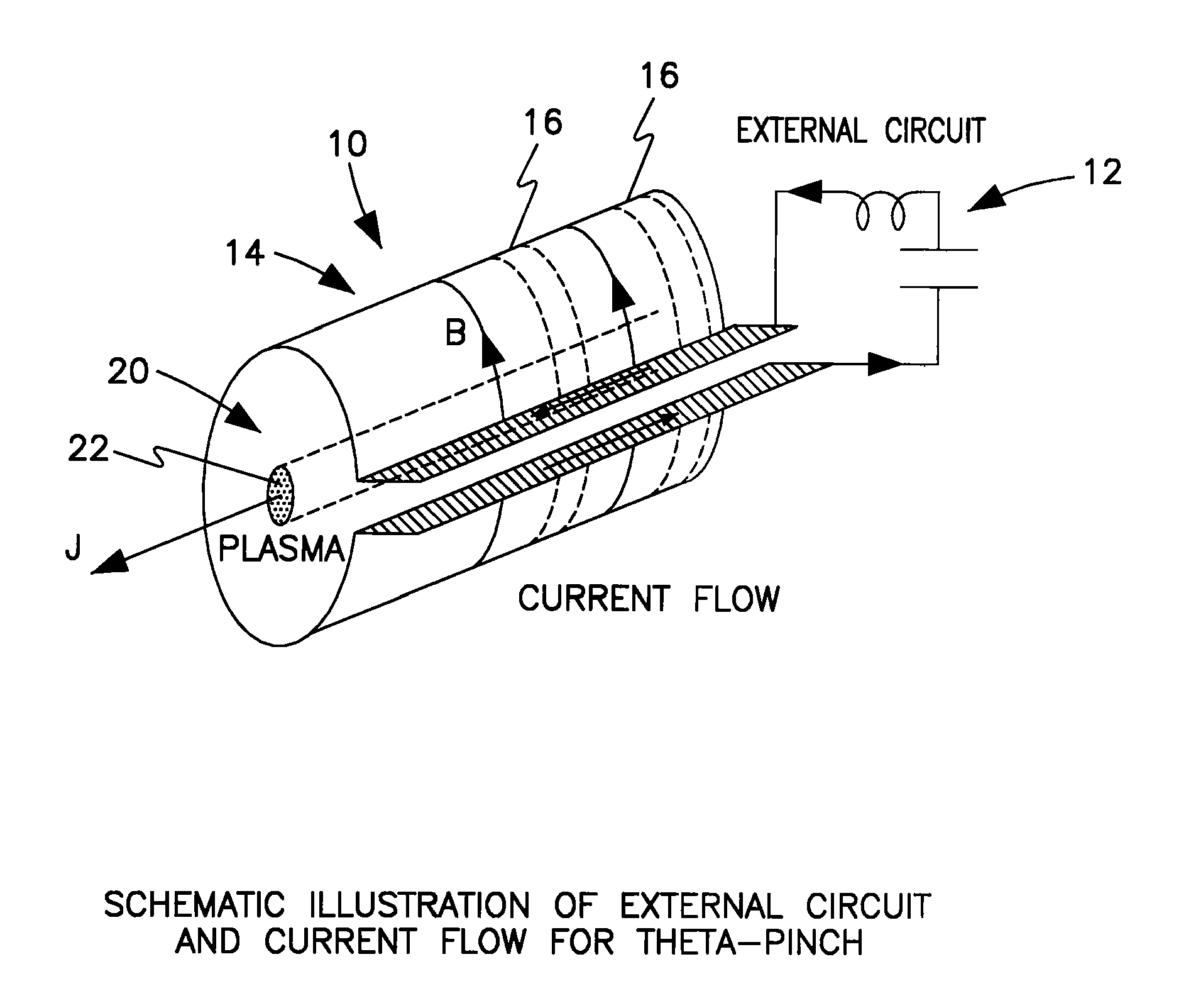
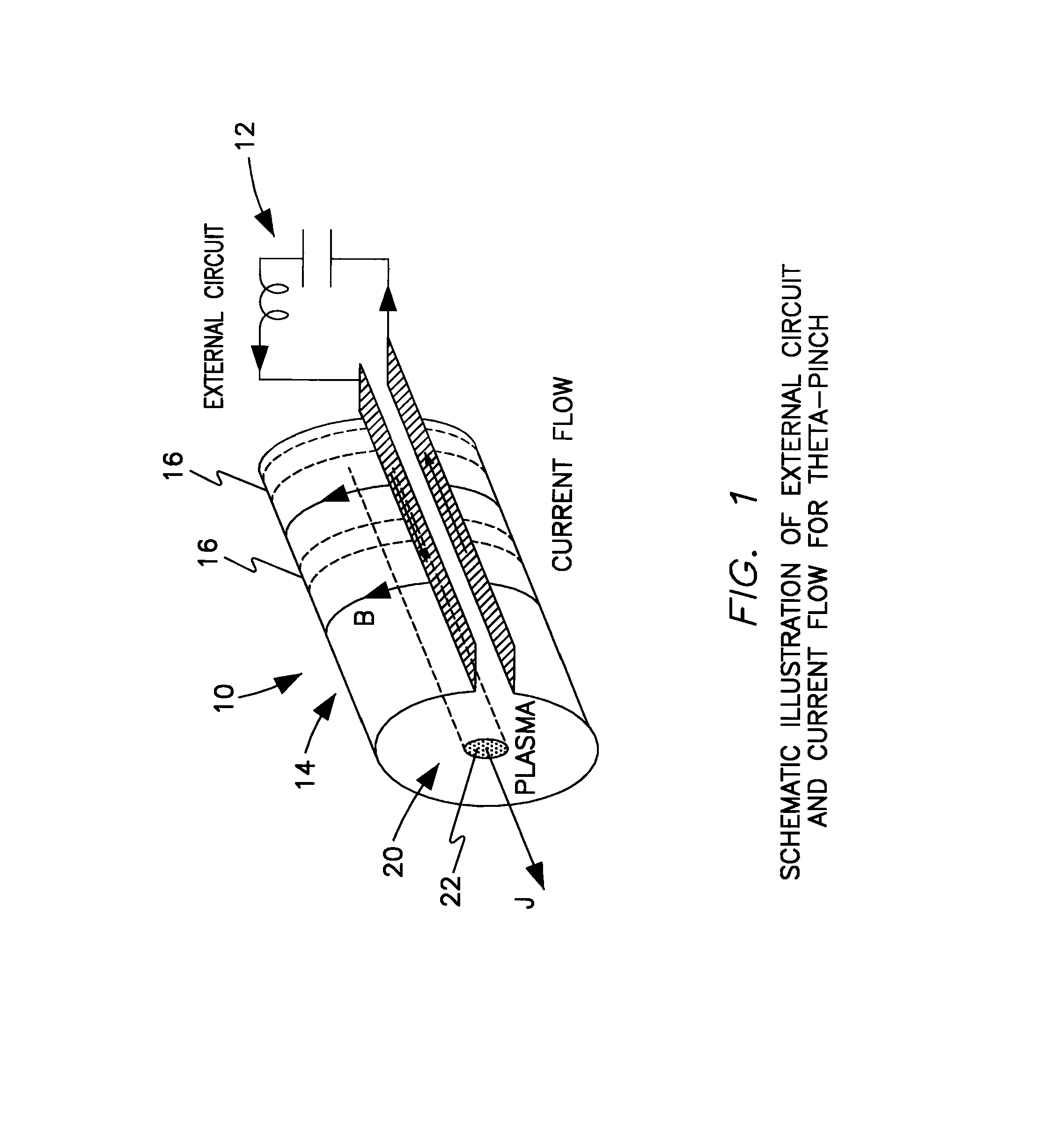
θ-Pinch

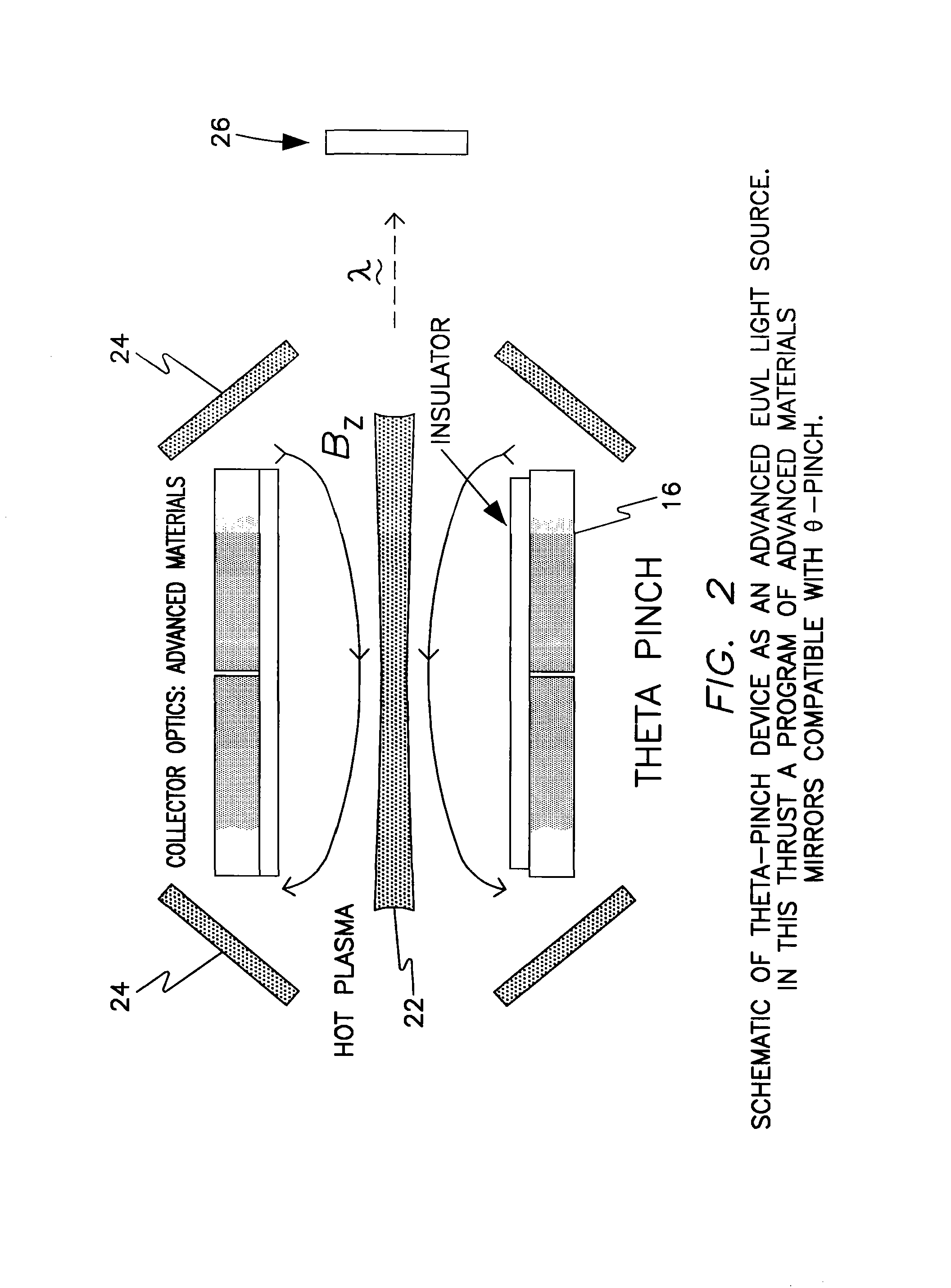
[0019]The θ-pinch EULV generating device of this invention is shown generally at 10 in FIG. 1 and FIG. 2. An electric circuit 12 provides power to the magnetic field generating mechanism 14 with coils 16. The magnetic field B 18 induces current component J within plasma generating zone 20. The plasma generating zone 20 contains a suitable gas, such as xenon, vaporized tin or vaporized lithium. The magnetic field B required to generate the temperature and currents of the this device is typically on the order of from about 7.5 kilo Gauss (kG) to about 10 kG (One Tesla). The resulting plasma 22 exists at a temperature from about 20 eV to about 40 eV. The hot plasma 22 generated by the magnetic field created by the flowing electric current accelerates the electrons and ions in the plasma into a tiny volume with sufficient energy to cause substantial stripping of outer electrons from the ions and a consequent production of x-rays and high energy ultraviolet radiation. The extremel...


PUM


Abstract

A device and method for generating extremely short-wave ultraviolet electromagnetic wave, utilizing a theta pinch plasma generator to produce electromagnetic radiation in the range of 10 to 20 nm. The device comprises an axially aligned open-ended pinch chamber defining a plasma zone adapted to contain a plasma generating gas within the plasma zone; a means for generating a magnetic field radially outward of the open-ended pinch chamber to produce a discharge plasma from the plasma generating gas, thereby producing a electromagnetic wave in the extreme ultraviolet range; a collecting means in optical communication with the pinch chamber to collect the electromagnetic radiation; and focusing means in optical communication with the collecting means to concentrate the electromagnetic radiation.

Description

[0001]This application claims priority from provisional application 60 / 545,492 filed Feb. 19, 2004.CONTRACTUAL ORIGIN OF INVENTION[0002]The United States Government has rights in this invention pursuant to Contract No. W-31-109-ENG-38 between the U.S. Department of Energy and the University of Chicago representing Argonne National Laboratory and under other contracts with Argonne.FIELD OF THE INVENTION[0003]This invention relates to an improvement in Extreme Ultraviolet Lithography (EUVL). More specifically this invention relates to a method and apparatus for producing the 13.5 nm wavelength radiation for Extreme Ultra Violet Lithography (EUVL).BACKGROUND OF THE INVENTIONDescription of Related Art[0004]The current process for chip making is called deep-ultraviolet lithography (DUV), which is a photography-like technique that focuses light through lenses to expose the raw circuit material and the accompanying photomask. Subsequent etching and chemical processing carves circuit patter...

Claims


Application Information

Patent Timeline
Patent Type & Authority Patents(United States)
IPC IPC(8): A61N5/06G01J3/10H05G2/00
CPCH05G2/003B82Y10/00G03F7/70033H05G2/005
Inventor HASSANEIN, AHMEDKONKASHBAEV, ISAKRICE, BRYAN
Owner THE UNITED STATES AS REPRESENTED BY THE DEPARTMENT OF ENERGY
Why Eureka
Try Eureka