Charged particle source and operation thereof

a technology of charge particle and charge source, which is applied in the direction of electric discharge lamps, ion beam tubes, coatings, etc., can solve the problems of limiting the use of such processes, not providing sufficient directionality control, and current charge particle sources that can only be optimized, so as to reduce the diameter of the associated aperture and increase the length of the aperture.

Active Publication Date: 2007-02-27
VEECO INSTR
View PDF15 Cites 49 Cited by
  • Summary
  • Abstract
  • Description
  • Claims
  • Application Information

AI Technical Summary

Benefits of technology

[0022]In a further aspect, the features of the present invention are accomplished by a ion optic grid assembly, comprising a set of one or more grid plates, the plate closest to the plasma, known as the “screen grid” having first and second surfaces and a plurality of parallel apertures exte

Problems solved by technology

Shortcomings in present charged particle sources will limit the use of such processes.
Although prior designs seek to control process uniformity, divergence angle and parallelism, current charged particle sources can usually only be optimized for one of these parameters, by compromising another.
For example, some known techniques for achieving highly uniform particle flux processes use conventional plasma-driven particle sources combined with substrate motion (such as planetary motion) to average out variations in the beam flux uniformity; these techniques do not provide sufficient control of the directionality, parallelism, or uniformity of the angular distribution of ion incidence across the substrate surface, but rather, for practically limited beam dimensions, tend to aggravate these problems by moving the substrate outside of the most parallel region of the beam.
However, the beam flux uniformity and charged particle angular distributions generated by conventional grid assemblies have unacceptable variations, due to variations in mechanical tolerances of the grid assembly and thermal

Method used


Image

  • Charged particle source and operation thereof
  • Charged particle source and operation thereof
  • Charged particle source and operation thereof

Examples


Embodiment Construction

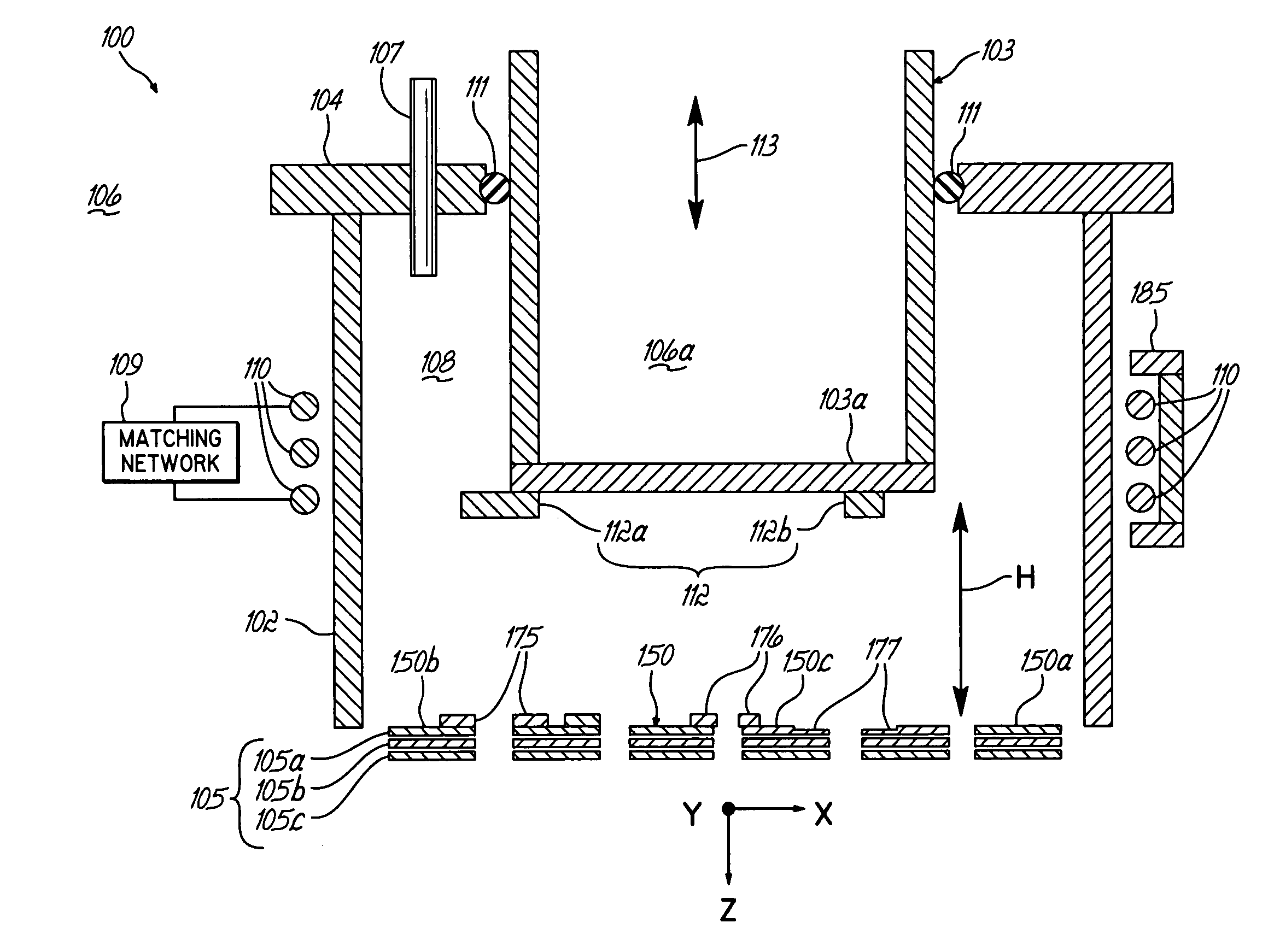
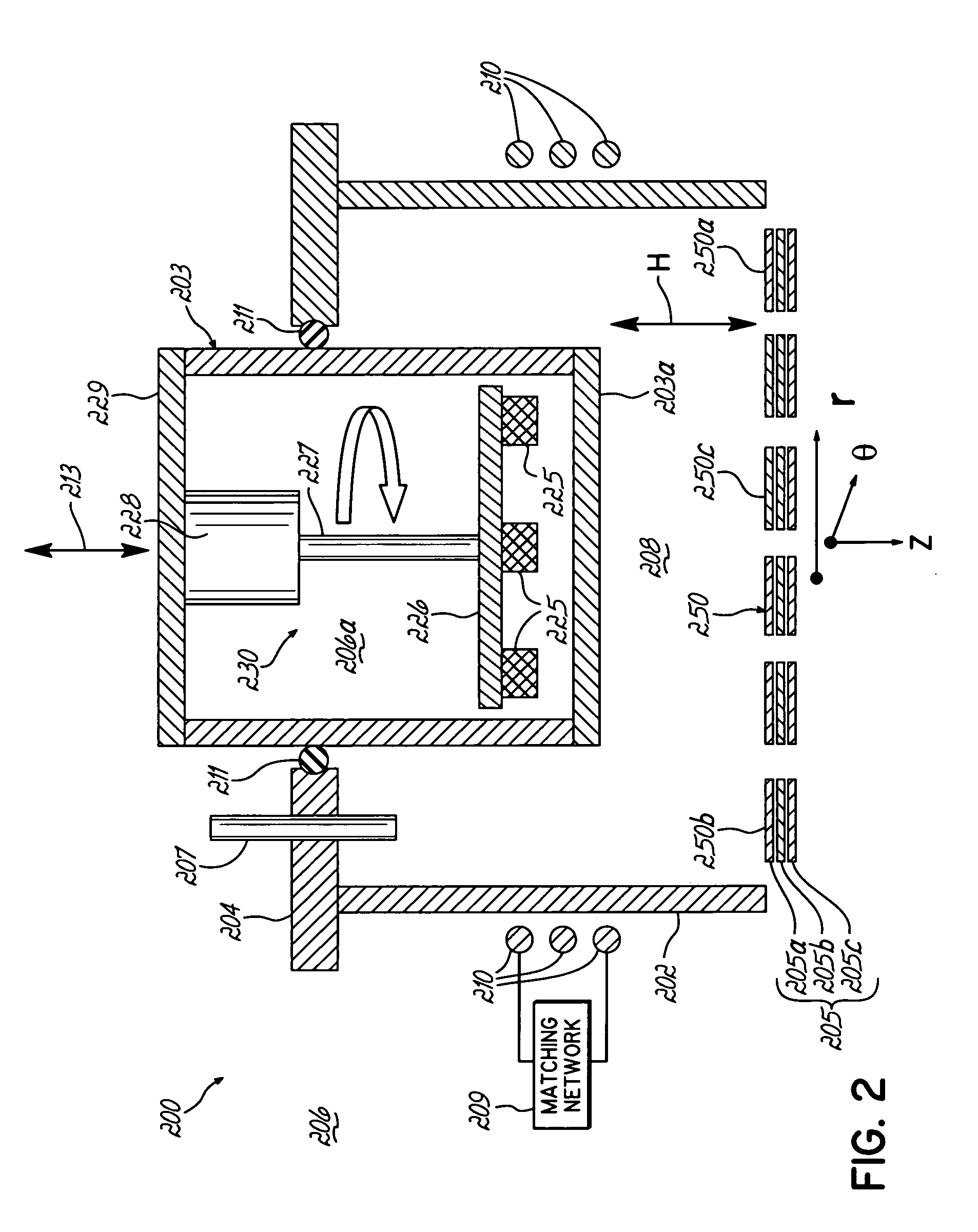
[0045]The present invention provides a charged particle source in which very low divergence beamlets are formed from particular ion optics structures of a gridded plasma-driven ion source. The source forms a broad collimated uniform beam from an array of charged particle beamlets, in which the beamlet current densities are uniform. Each beamlet has a very small angular divergence, the beamlet divergence is very uniform, and the mean direction vectors of the beamlets are very parallel across the usable area of the source. The charged particle current density profile is also optimizable for processes in which the substrate is moved in front of the beam during the process, so that the substrate motion attains a very uniform particle treatment.

[0046]Referring to FIG. 1: The ion source described by our invention, 100, consists of a radio frequency (rf) Inductively coupled Plasma (RF ICP) discharge chamber and ion optic assembly mountable to a high vacuum substrate processing chamber. In ...


PUM

PropertyMeasurementUnit
Shapeaaaaaaaaaa
Frequencyaaaaaaaaaa
Energyaaaaaaaaaa

Abstract

A charged particle source utilizes a novel plasma processing chamber, RF coil and ion optics, to achieve high uniformity. The plasma processing chamber has a re-entrant vessel which is movable, and which includes extensions of adjustable shape or position, to make more uniform the plasma contained within the chamber. One or more magnets, which may be static or moving, may be included within the re-entrant vessel. The ion optics include a grid with a number of apertures, and tuning features each surrounding an aperture. These tuning features either reduce the diameter of the associated aperture, or increase the length of that aperture, to create more uniform beamlets emerging from the grid. The RF coil includes a flux concentrator positioned adjacent to the winding in at least one angular region thereof to tune the magnetic field produced thereby.

Description

CROSS REFERENCE TO RELATED APPLICATIONS[0001]The present application claims benefit of U.S. provisional application Ser. No. 60 / 444,731, filed Feb. 4, 2003, the disclosure of which is hereby incorporated herein by reference in its entirety.FIELD OF THE INVENTION[0002]The present invention relates to charge particle sources such as are used for treatment of a substrate.BACKGROUND OF THE INVENTION[0003]Charged particle treatment of substrates is used in a variety of applications. One specific application is ion beam etching of substrates having features with extreme critical dimension uniformity and symmetry requirements, in particular, “pole trimming” and “pole slimming” processes used in formation of a thin film magnetic head for a disk drive. In such processes, the substrate, depending on the particular application, is positioned at one or more angles to the beam, between normal incidence (0°) and glancing incidence (e.g. about 70°). Depending on the application, the substrate may ...

Claims


Application Information

Patent Timeline
IPC IPC(8): H01J7/24H01J37/32H01L21/00
CPCH01J27/18H01J37/321H01L21/67253H01L21/67069H01J37/32458
Inventor KANAROV, VIKTORHAYES, ALAN V.YEVTUKHOV, RUSTAMREISS, IRAFREMGEN, JR., ROGER P.CELARU, ADRIANWILLIAMS, KURT E.BORGES, CARLOS FERNANDO DE MELLODRUZ, BORIS L.RAJAN, RENGAHEGDE, HARI
Owner VEECO INSTR
Why Eureka
Try Eureka