Delay locked loop circuit for internally correcting duty cycle and duty cycle correction method thereof

a technology of delay locking loop and duty cycle, which is applied in the direction of pulse technique, generating/distributing signals, instruments, etc., can solve the problems of limiting the operating frequency, power consumption increasing, and dcc not performing properly, so as to achieve the effect of improving memory device characteristics, reducing power consumption, and reducing power consumption

Inactive Publication Date: 2007-02-27
SAMSUNG ELECTRONICS CO LTD
View PDF16 Cites 43 Cited by
  • Summary
  • Abstract
  • Description
  • Claims
  • Application Information

AI Technical Summary

Benefits of technology

[0012]The present invention provides a delay locked loop (DLL) circuit having a duty cycle corrector (DCC) that preferably has a broad range of dut

Problems solved by technology

If the duty cycle of an external clock signal ECLK has a ratio of 40 to 60 or a ratio of 60 to 40, th

Method used


Image

  • Delay locked loop circuit for internally correcting duty cycle and duty cycle correction method thereof
  • Delay locked loop circuit for internally correcting duty cycle and duty cycle correction method thereof
  • Delay locked loop circuit for internally correcting duty cycle and duty cycle correction method thereof

Examples


Embodiment Construction

[0037]The present invention now will be described more fully with reference to the accompanying drawings, in which preferred embodiments of the invention are shown.

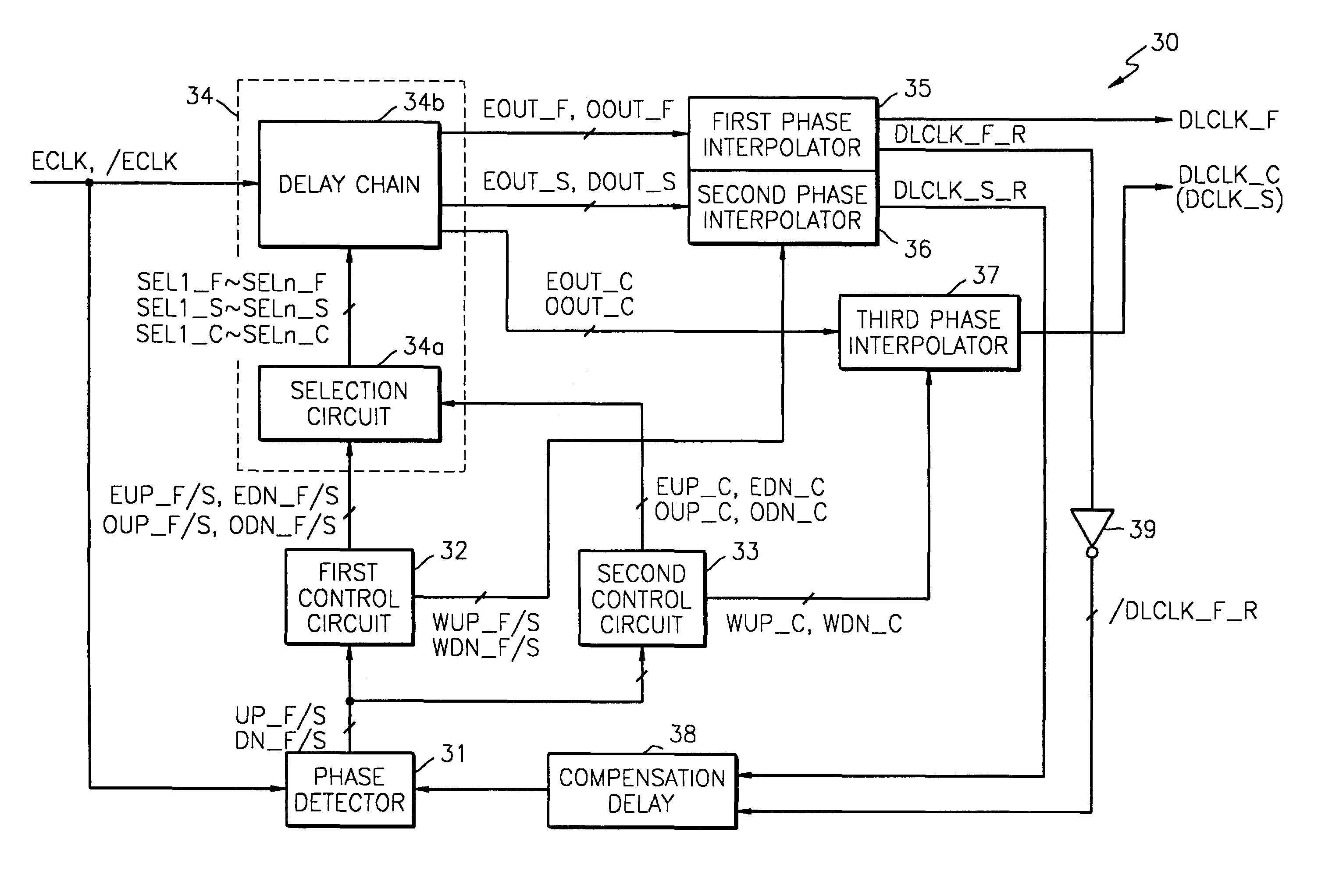
[0038]FIG. 3 is a block diagram of a DLL30 having a duty cycle corrector (DCC) according to an embodiment of the present invention. Referring to FIG. 3, DLL30 includes a phase detector 31, a first control circuit 32, a second control circuit 33, a delay line unit 34, a first phase interpolator 35, a second phase interpolator 36, a third phase interpolator 37, and a compensation delay 38.

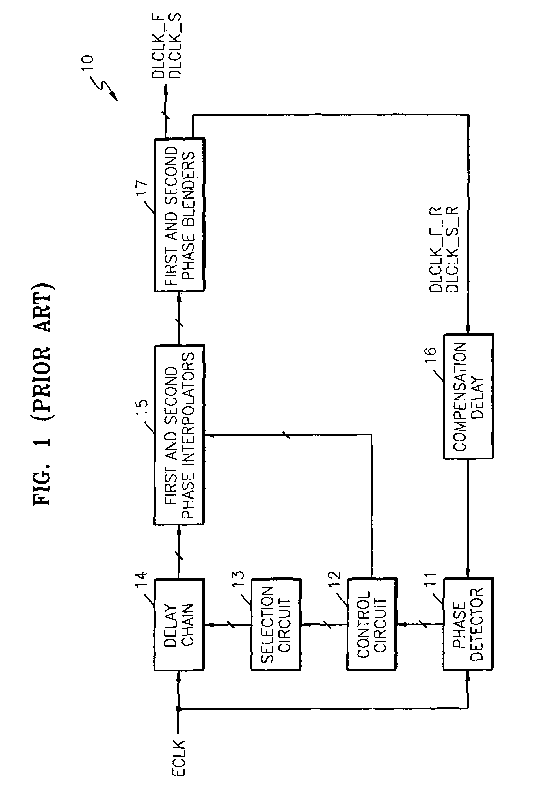
[0039]DLL30 is capable of correcting duty cycle. The conventional DLL for a double data rate (DDR) system includes two loops to control a rising edge and a falling edge and includes a phase blender to correct the duty cycle. In contrast, in DLL30, another loop is included, instead of the phase blender, to correct the duty cycle. That is, the second control circuit 33 and the third phase interpolator 37 are added to the conventional DLL of ...


PUM


Abstract

A delay locked loop (DLL) circuit having a duty cycle corrector (DCC) that has a broad range of duty cycle correction, consumes only a small amount of power, has few restrictions on operating frequency, and improves the characteristics of a memory device is described. The delay locked loop circuit includes an additional loop for duty cycle correction as well as loops for controlling a rising edge and a falling edge of output signals. Thus, the delay locked loop circuit can internally correct the duty cycle without the use of a phase blender.

Description

BACKGROUND OF THE INVENTION[0001]This application claims the priority of Korean Patent Application No. 2002-60814, filed 5 Oct. 2002, in the Korean Intellectual Property Office, the disclosure of which is incorporated herein in its entirety by reference.[0002]1. Field of the Invention[0003]The present invention relates to a delay locked loop (DLL) circuit, and more particularly, to a DLL for internally correcting a duty cycle and a duty cycle correction method thereof.[0004]2. Description of the Related Art[0005]In data transmission such as between a memory device and a memory controller where data is transmitted after the data is synchronized with a clock signal, bus load and transmission frequency have increased. Thus, it is increasingly important to synchronize the data with the clock signal. That is, the time required to load the data onto the bus in response to the clock signal is compensated for to place the data at edges or centers of the clock signal. Between a phase locked ...

Claims


Application Information

Patent Timeline
IPC IPC(8): H03D3/24H03L7/06G06F1/04G11C11/407G11C11/4076H03K5/04H03K5/13H03K5/156H03L7/08H03L7/081H03L7/089H04L7/033
CPCH03K5/13H03L7/0814H03K5/1565H03L7/089H03L7/0818H03L7/0816H03L7/08
Inventor CHO, GEUN-HEEKIM, KYU-HYOUN
Owner SAMSUNG ELECTRONICS CO LTD
Why Eureka
Try Eureka