Radiation detector with converters

a converter and radiation detector technology, applied in the direction of photometry, optical radiation measurement, instruments, etc., can solve the problems of limiting the conversion efficiency of the detector, limiting the efficiency of the ionization detector, and the manufacture of the transparent scintillating converter plate b>26/b>′ using such high-quality scintillators, so as to avoid the reabsorption of electrons

Inactive Publication Date: 2007-03-06
WISCONSIN ALUMNI RES FOUND
View PDF9 Cites 53 Cited by
  • Summary
  • Abstract
  • Description
  • Claims
  • Application Information

AI Technical Summary

Benefits of technology

[0015]The present inventors have recognized that the height limitation of the converter plate, such that avoids reabsorption of electrons, may be overcome by breaking the converter plate into a plurality of axially extending converter elements. High-energetic electrons and, depending on the energy of the incident radiation, other positive and negative charge carriers, exit the converter material into the detector volumes placed between the converter elements. Converter elements may now be of arbitrary height in the longitudinal direction with electrons generated both at the top of the converter and the bottom of converter likewise liberated only a short distance, through the converter element into the detector. In this way, the problem of electrons being retained by the converter as it increases in height is substantially eliminated and converter height sufficient to convert substantially all MeV x-rays can be contemplated.

Problems solved by technology

The ionization detector 10 of FIG. 1 would not be expected to be efficient for MeV x-rays which would be expected to pass fully through any practical thickness of xenon, generating relatively few electrons.
Generally, however, the height 30 of the converter plate 26 is limited to less than that required to filly absorb the MeV x-rays 24 correspondingly limiting the conversion efficiency of the detector 25.
Unfortunately, the manufacture of transparent scintillating converter plate 26′ using such high quality scintillators is significantly more expensive than the manufacture of conventional converter plate 26 shown in FIG. 2a and the efficiencies of such radiation detectors remain modest.

Method used


Image

  • Radiation detector with converters
  • Radiation detector with converters
  • Radiation detector with converters

Examples


Embodiment Construction

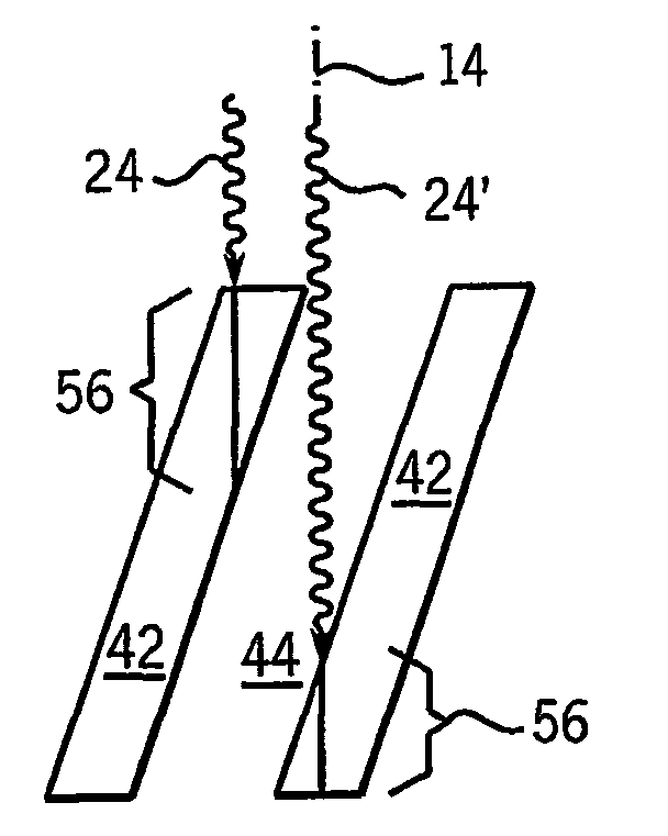
[0042]Referring now to FIG. 3, a detector 40 of the present invention provides for a series of longitudinally extending converter elements 42 aligned generally with the local radiation axis 14 of radiation propagation. The converter elements 42 may be, for example, planar vanes or may be rods or other shapes.

[0043]Converter elements 42 are separated from each other in a direction transverse to the radiation axis 14 to create interconverter volumes 44 such as may be filled with an ionizing medium such as a gas including, for example, xenon. The gas may be compressed in a housing (not shown) so as to increase the odds of electron-gas interaction in the interconverter volumes 44.

[0044]MeV x-rays 24 received by the detector 40 strike the converter elements 42 to produce high-energetic electrons 46 which proceed into the interconverter volumes 44. The electrons ionize the gas in the interconverter volumes 44. Some MeV x-rays 24′ will pass completely through interconverter volumes 44 with...


PUM


Abstract

A high efficiency radiation detector employs longitudinally extending converter elements receiving longitudinally propagating radiation to produce high-energetic electrons received by detector structures in interstitial spaces. The secondary electron generation in this architecture allows great freedom in selection of converter materials and thickness. A variety of detector mechanisms may be used including ionization-type detectors or scintillation-type detector.

Description

CROSS REFERENCE TO RELATED APPLICATIONS[0001]This application is based on provisional application 60 / 299,097 filed Jun. 18, 2001, and PCT application PTC / US / 02 / 19154 filed Jun. 17, 2002 and entitled “Radiation Detector with Laterally Acting Converters” and claims the benefit thereof.STATEMENT REGARDING FEDERALLY SPONSORED RESEARCH OR DEVELOPMENT[0002]Not Applicable.BACKGROUND OF THE INVENTION[0003]Highly efficient photon detectors play a major role in countless applications in physics, nuclear engineering and medical physics. In nuclear engineering, radioactive waste can be characterized with photon detectors using nondestructive assay techniques (PNDA). In medical physics, photon detectors are extensively used for diagnostic x-ray and CT imaging, nuclear medicine, and quite recently, radiation therapy of cancer.[0004]In radiation therapy of cancer, ever more accurate delivery techniques spur the need for efficient detectors for million electron volt (MeV) photons in order to allow ...

Claims


Application Information

Patent Timeline
Patent Type & Authority Patents(United States)
IPC IPC(8): G01T1/185H01J47/04G01T1/00G01T1/164G01T1/24G01T1/29
CPCG01T1/1644G01T1/24G01T1/2935G01T1/2928G01T1/29G01T1/185
Inventor HINDERER, RALFKELLER, HARALDMACKIE, THOMAS R.KAPATOES, JEFFREYPEARSON, DAVID W.RECKWERDT, PAUL J.SCHMIDT, RICHARD C.
Owner WISCONSIN ALUMNI RES FOUND
Why Eureka
Try Eureka