Impedance-matching apparatus and construction for intravascular device

a technology of impedance matching and construction, which is applied in the field of intravascular devices, can solve the problems of not being able to easily incorporate into the design of the device, the device is relatively large, and the impedance matching is not ideal for intravascular navigation, so as to improve the impedance matching effect, facilitate manufacturing, and improve the effect of impedance matching

Inactive Publication Date: 2007-03-20
BOSTON SCI SCIMED INC
View PDF46 Cites 83 Cited by
  • Summary
  • Abstract
  • Description
  • Claims
  • Application Information

AI Technical Summary

Benefits of technology

[0009]The present invention relates to elongated intravascular devices adapted to be advanced through a vessel of a subject. The present invention provides one or more constructions of MR catheters that improve impedance matching and / or are easier to manufacture in a fast and reliable manner.

Problems solved by technology

However, for intravascular coils, miniaturization of the tuning capacitors is necessary.
But such components are bulky and are not easily incorporated into the design of the device.
However, these circuits still result in a relatively large device that is not ideal for intravascular navigation.
Also, the circuits require many connections and the fabrication process is relatively complex.
Another problem that arises with intravascular MRI antennas and intravascular guidewires used in conjunction with an MRI system is that the electrical conductors tend to pick up the RF signals from the MRI system.
This results in a higher voltage on the conductors and unwanted heating of the conductors.
However, since the shields are made from metallic conductors, some heating of the conductors still occurs.
In addition, general construction difficulties also present problems.
Simply connecting the antenna back to the transmission line conductors in such a small environment is quite difficult.

Method used


Image

  • Impedance-matching apparatus and construction for intravascular device
  • Impedance-matching apparatus and construction for intravascular device
  • Impedance-matching apparatus and construction for intravascular device

Examples


Embodiment Construction

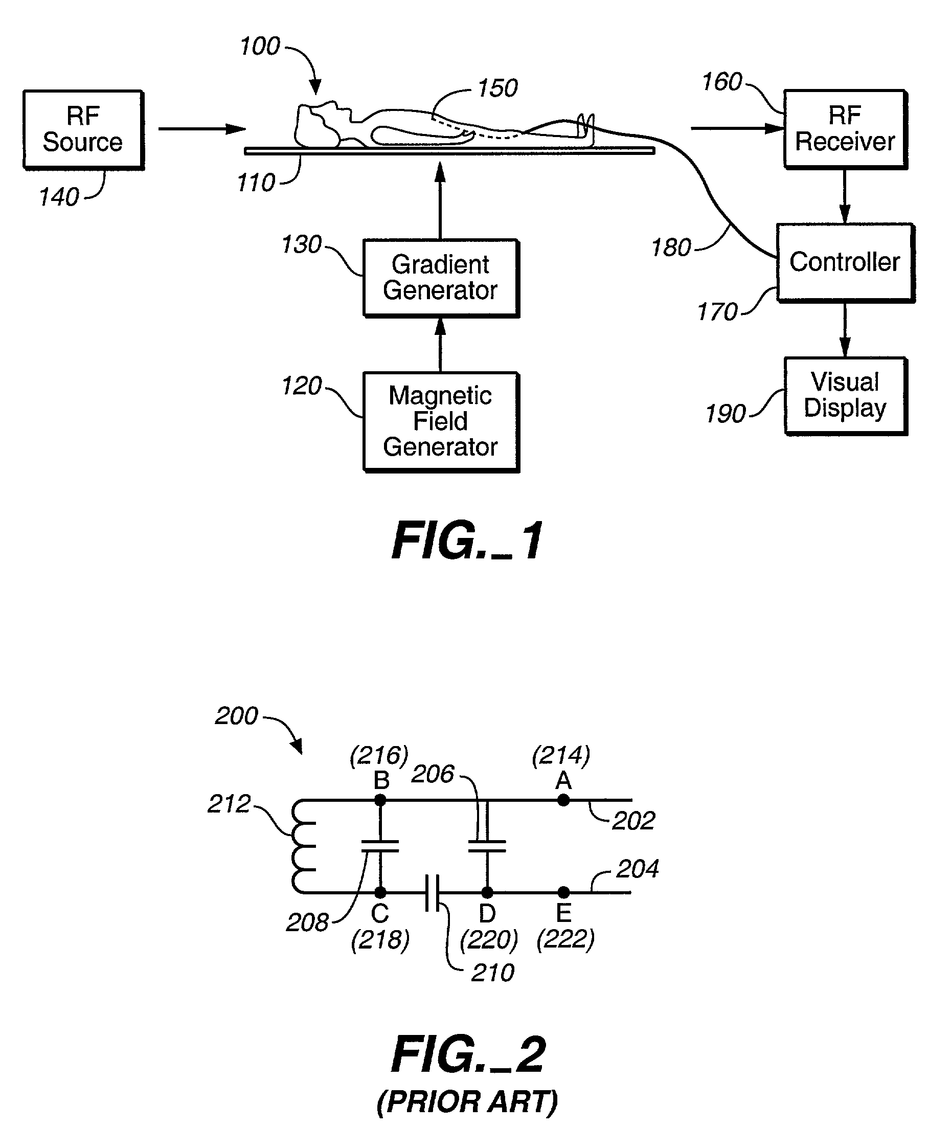
[0030]FIG. 1 is a partial block diagram of an illustrative magnetic resonance imaging and intravascular guidance system in which embodiments of the present invention could be employed. In FIG. 1, subject 100 on support table 110 is placed in a homogeneous magnetic field generated by magnetic field generator 120. Magnetic field generator 120 typically comprises a cylindrical magnet adapted to receive subject 100. Magnetic field gradient generator 130 creates magnetic field gradients of predetermined strength in three mutually orthogonal directions at predetermined times. Magnetic field gradient generator 130 is illustratively comprised of a set of cylindrical coils concentrically positioned within magnetic field generator 120. A region of subject 100 into which a device 150, shown as a catheter, is inserted, is located in the approximate center of the bore of magnet 120.

[0031]RF source 140 radiates pulsed radio frequency energy into subject 100 and the MR active sample within device ...


PUM


Abstract

Intravascular device for matching impedances of portions of an intravascular circuit and limiting RF signal-induced heating of intravascular conductors. An intravascular device includes alternating conductive and dielectric layers and an electrically conductive coil in a configuration that effects an impedance-matching circuit. Another embodiment of an intravascular device has cylindrical inner and outer walls formed of an expandable, electrically conductive material, the inner and outer walls being separated by a compressible dielectric material. Varying the pressure in the lumen defined by the inner wall changes the spacing between the inner and outer walls, thereby changing the capacitance between the inner and outer wall. Another embodiment of an intravascular device includes one or more coaxial chokes for limiting heating caused by currents induced by RF signals. A conductive shield of the choke is formed of a conductive polymer to further reduce heating effects. Other embodiments include different transmission lines and antenna structures.

Description

BACKGROUND OF THE INVENTION[0001]The present invention relates generally to intravascular devices. More particularly, the present invention relates to impedance-matching among segments and construction of a transmission line associated with such an intravascular device.[0002]Tracking of catheters and other devices positioned within a body may be achieved by means of a magnetic resonance imaging (MRI) system. Typically, such a magnetic resonance imaging system may be comprised of magnet, a pulsed magnetic field gradient generator, a transmitter for electromagnetic waves in radio frequency (RF), a radio frequency receiver, and a controller. In a common implementation, an antenna is disposed either on the device to be tracked or on a guidewire or catheter (commonly referred to as an MR catheter) used to assist in the delivery of the device to its destination. In one known implementation, the antenna comprises an electrically conductive coil that is coupled to a pair of elongated electr...

Claims


Application Information

Patent Timeline
Patent Type & Authority Patents(United States)
IPC IPC(8): A61B6/00A61B5/055A61B5/06A61B17/00
CPCA61B5/055A61B5/06A61B2017/00292
Inventor TALPADE, DNYANESHSMITH, SCOTT R.EDMUNDS, KEVIN D.LARSON, KENNETH R.
Owner BOSTON SCI SCIMED INC
Why Eureka
Try Eureka