Making composite material parts from blanks made by reinforcing a fiber structure and/or bonding fiber structures together

a technology of fiber structure and composite material, which is applied in the direction of manufacturing tools, ceramic layered products, transportation and packaging, etc., can solve the problems of insufficient or difficult to perform needleing, rigid fiber structure, and relatively unsuitable for being shaped, so as to achieve simple shape, high pin implantation density, and simplified industrial process

Active Publication Date: 2007-04-10
SN DETUDE & DE CONSTR DE MOTEURS DAVIATION S N E C M A
View PDF8 Cites 23 Cited by
  • Summary
  • Abstract
  • Description
  • Claims
  • Application Information

AI Technical Summary

Benefits of technology

[0024]This leads to several significant advantages compared with implantation being performed on dry fiber structures or structures that have been preimpregnated with a resin or that have already densified by a cured resin.
[0025]In a consolidated fiber structure, the fibers are bonded to one another so the pins can be implanted without deforming the fiber structure and without it being necessary to keep the fiber structure in tooling to avoid it being deformed.
[0026]In addition, the fiber structure can be consolidated after being shaped. The implantation density of the pins can then be high since the problem of the ability of the reinforced structure to deform no longer arises.
[0027]Particularly when making blanks of complex shape, the industrial process is simplified. Blanks can be made by assembling together fiber structures that are simple in shape and that can easily be consolidated separately and beforehand.
[0028]In addition, since a consolidated fiber structure is partially densified, the pins are better held in place after they have been implanted than is the case for a dry structure in which the fibers remain free.

Problems solved by technology

Nevertheless, needling can be insufficient or difficult to perform.
In particular, when using ceramic fibers, for example, needling can have a destructive effect on the fibers, thereby weakening the reinforcement in the plane of the plies.
Nevertheless, good mechanical strength in the Z direction requires a high concentration of bonds between layers, which leads to a fiber structure that is rigid, and relatively unsuitable for being shaped, even when shaping requires deformation of limited amplitude only.
This drawback is also to be found with fiber structures that are built up from plies that are bonded together by stitching.
In addition, for ceramic fiber structures, it is difficult to use a ceramic thread for stitching plies together.
Furthermore, when the parts that are to be manufactured are complex in shape, it can be difficult or even impossible to make a one-piece preform having a shape close to that of the part that is to be manufactured.
Such a method is restricted to manufacturing composite materials having an organic matrix.
Unfortunately, for thermostructural composite material parts that are to be exposed in operation to temperatures that are very high, the use of metal pins is undesirable, either because of the reduced strength of metal at such temperatures, or else because of differential expansion between the metal and the ceramic or carbon components of the composite material.
In addition, the use of large-diameter pins can be undesirable because of the non-uniformity they impart to the structure of the composite material.
However, with a set of fiber plies or with a plurality of sets of plies that have been joined together, that cannot suffice to confer sufficient strength to enable them to be handled without being deformed.
It is then necessary to use tooling in order to conserve the desired shape prior to densifying the fiber plies, which can be expensive and difficult to achieve, particularly when the composite material parts to be made are complex in shape.

Method used


Image

  • Making composite material parts from blanks made by reinforcing a fiber structure and/or bonding fiber structures together
  • Making composite material parts from blanks made by reinforcing a fiber structure and/or bonding fiber structures together

Examples


example 1

[0098]Two fiber plates were formed, each by stacking five layers of SiC plain weave fabric made up of SiC yarn such as that sold under the name “Hi-Nicalon” by the Japanese supplier Nippon Carbon. The resulting fiber plates had a pore volume ratio equal to about 60%.

[0099]The fiber plates were consolidated by forming a PyC interphase and depositing SiC by chemical vapor infiltration, and the pore volume ratio after consolidation was reduced to about 50%.

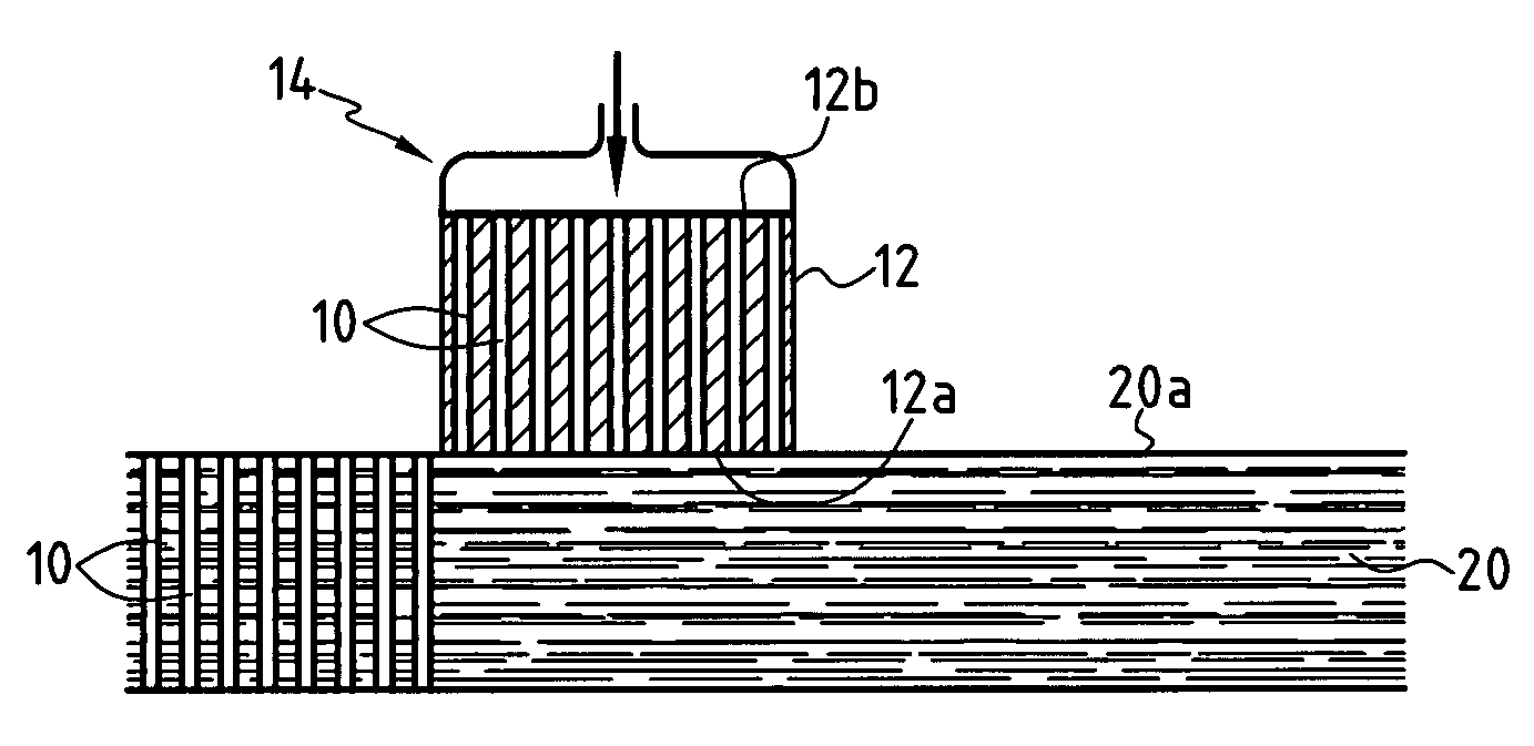
[0100]Pins were made by stiffening a 500 filament SiC yarn supplied by the Japanese supplier Nippon Carbon, with stiffening being achieved by densifying with a BMI resin. The diameter of the pins was about 0.4 mm.

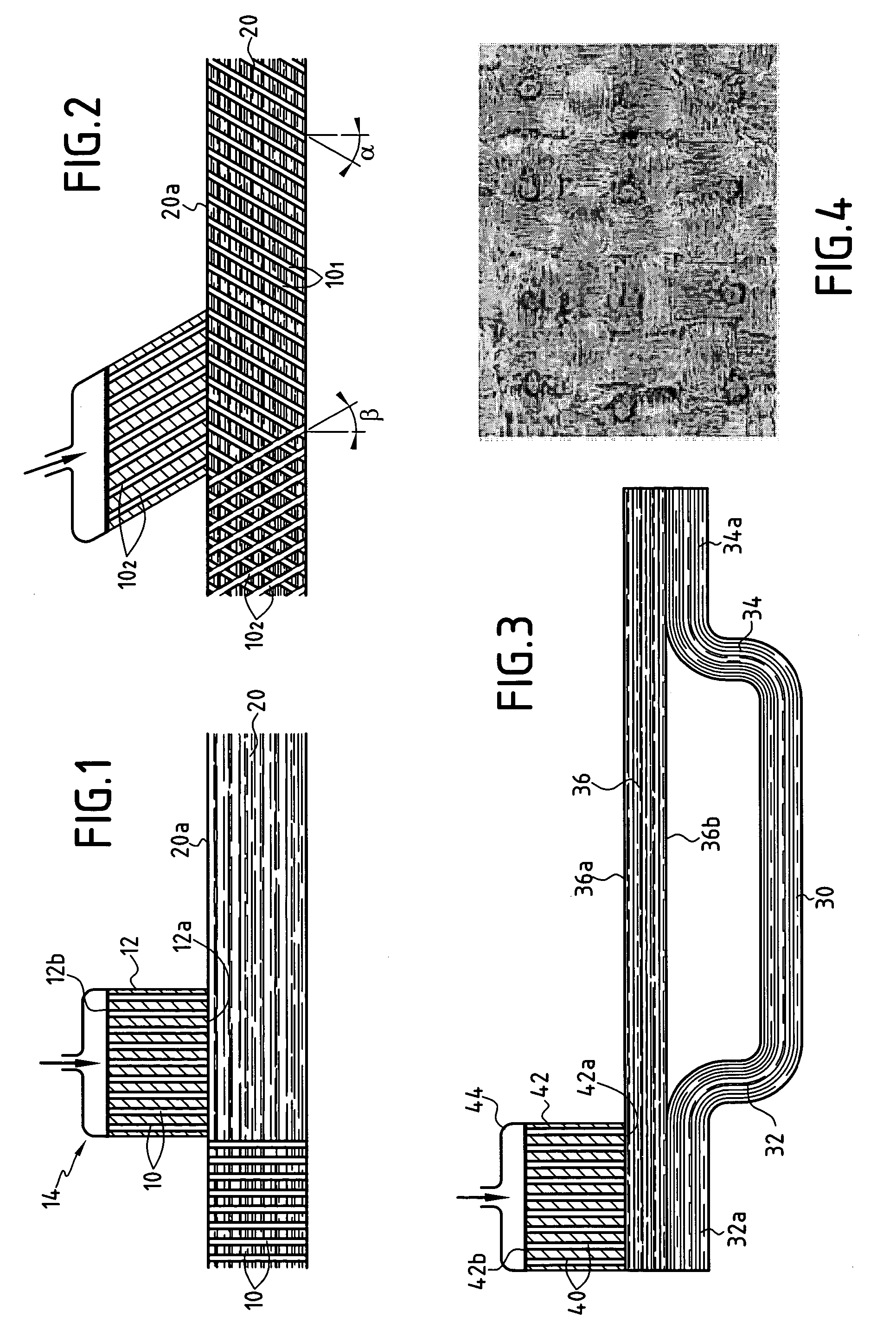
[0101]The pins were implanted through the superposed consolidated fiber plates at a density of 16 pins per square centimeter (cm2). The photograph of FIG. 4 shows the surface of the resulting fiber blank. Implanting the pins did not raise any particular difficulties.

[0102]The blank fitted with the pins was densified by an Si...

example 2

[0106]A fiber structure was made in the form of a multilayer cloth obtained by three-dimensional weaving of “Hi-Nicalon” SiC fiber yarn, such as that used in Example 1. The three-dimensional fabric comprised ten layers with a pore volume ratio equal to about 65%.

[0107]The fiber structure was consolidated as in Example 1, with the pore volume ratio after consolidation being reduced to about 55%.

[0108]Pins of the same kind as in Example 1 were implanted in the consolidated fiber structure at a density of 16 pins / cm2.

[0109]The resulting blank was then densified with an SiC matrix by chemical vapor infiltration.

example 3

[0110]The procedure was the same as in Example 2, but pins were implanted at a density of 32 pins / cm2.


PUM

PropertyMeasurementUnit
temperatureaaaaaaaaaa
pressureaaaaaaaaaa
diameteraaaaaaaaaa

Abstract

A porous fiber structure is consolidated by forming within a deposit of a refractory material by partially densifying the fiber structure in such a manner as to bond together the fibers of the fiber structure so as to enable the fiber structure to be handled without being deformed, while leaving empty the major fraction of the initial pore volume of the fiber structure, and rigid pins are implanted through the consolidated porous structure. A blank is obtained by reinforcing a fiber structure by implanting pins or by bonding together consolidated fiber structures, the bonding being performed by implanting pins. A composite material part is obtained by densifying the blank.

Description

[0001]Making a blank by reinforcing a fiber structure and / or bonding fiber structures together, and use in making composite material parts.[0002]This application claims priority to a French patent application No. 03 02614 filed Mar. 4, 2003.BACKGROUND OF THE INVENTION[0003]The present invention relates to making composite material parts from fiber blanks made from one or more porous fibrous structures, in particular thermostructural composite material parts.[0004]Thermostructural composite materials are remarkable for their good mechanical properties and for their ability to conserve these properties at high temperatures. They are used in particular for making structural parts in the fields of aviation and space. Typical examples of thermostructural materials are carbon / carbon (C / C) composite materials comprising carbon fiber reinforcement densified by a carbon matrix, and ceramic matrix composite (CMC) materials. CMC materials comprise fiber reinforcement made of refractory fibers ...

Claims


Application Information

Patent Timeline
Patent Type & Authority Patents(United States)
IPC IPC(8): B23B7/08D06H5/00B29C65/00B29C65/56B29C70/24B32B5/02B32B5/10B32B5/26B32B18/00C04B35/565C04B35/80D04H1/42D04H1/4242D04H1/498D04H1/645D04H3/002
CPCB29C65/564B29C66/131B29C66/721B29C70/24B32B5/10B32B5/26B32B18/00C04B35/565C04B35/62873C04B35/62884C04B35/806D04H1/42D04H1/4242D04H1/498D04H1/645D04H3/002B29C66/112B29C65/00Y10T29/49833C04B2235/5244C04B2235/5252C04B2235/614C04B2235/77C04B2237/365C04B2237/38C04B2237/584B29C66/7212B29C66/72141B29C66/72143B29C66/73755B29C66/7394C04B35/80Y10T428/249923B29K2307/04B29C65/56B29C69/00B32B5/22B32B7/08C04B35/82C04B35/83
Inventor BOUILLON, ERICCOUPE, DOMINIQUEBOUVIER, REMIPHILIPPE, ERIC
Owner SN DETUDE & DE CONSTR DE MOTEURS DAVIATION S N E C M A
Why Eureka
Try Eureka