High throughput plasma treatment system

a plasma treatment and high throughput technology, applied in the direction of conveyor parts, transportation and packaging, coatings, etc., can solve the problems of reducing productivity, limiting the scope of operation of both embodiments, and picking up mechanisms, so as to improve the flow of plasma, speed up processing time, and increase the throughput of parts multiplicatively

Inactive Publication Date: 2007-04-10
NORDSON CORP
View PDF72 Cites 5 Cited by
  • Summary
  • Abstract
  • Description
  • Claims
  • Application Information

AI Technical Summary

Benefits of technology

[0033]An advantage of the present invention is that a plurality of parts may be subjected to plasma treatment simultaneously in an in-line fashion, thereby speeding up processing time.
[0034]Another advantage of the invention is that none of the moving parts of the system are subjected to degradation from plasma reaction.
[0035]A further advantage is that the system is entirely automated, thereby providing hands-free operation.
[0036]Yet another advantage of the invention is that parts may be loaded within the reaction chamber on multiple levels, thereby multiplicatively increasing the throughput of parts.
[0037]An additional advantage of the invention is that vertically oriented electrodes permit better flow of the plasma over parts which are horizontally placed, and thus more uniformity of treatment of the parts is achieved.
[0038]Another advantage of the present invention is that by using an increased DC bias, there is better penetration of the plasma between parts in multilevel arrays.

Problems solved by technology

Batch-wise treatment also reduces productivity by interrupting the flow of processing and assembly of parts.
However, both of the embodiments disclosed are much more limiting in their scope of operation than is desirable.
In addition, pick-up mechanisms of the type shown in Uehara, which as noted is in the form of a suction device, are known to be not entirely free from droppage and breakage of parts due to temporary loss or irregularity of vacuum pressure.
Hijikata eliminates the precarious suction pick-up arrangement of Uehara, but again fails to offer an option for treating more than one part at a time in an in-line fashion.
Nor is the invention of Hijikata amenable to such, since even were more than one part crudely loaded onto the ends of the sliding arms of the apparatus, no mechanism is available for properly spacing the parts upon the wafer table, such spacing being critical when more than one part is subjected to plasma treatment.
The enclosed nature of these chambers necessarily limits the number of parts that can be treated before the chambers have to be opened for loading a new batch to be processed.
Additionally, the configuration of the input gate allows a very limited number of parts to be treated at once, and consequentially, the throughput of this system can be expected to be likewise limited.
Both of these variations can be expected to have problems related to the use of moving parts within the plasma chamber.
Moving parts typically require lubricants, which can, over time, contaminate the etching chamber and the treated parts.
Additionally, when moving parts are exposed to conditions such as in a plasma etching chamber, these parts are susceptible to corrosion.
Moving parts which operate on fine tolerances can be expected to require frequent replacement when exposed to such harsh operating conditions.
These moving parts can be expected to experience the same difficulties of contamination and corrosion discussed above.
Additionally, the throughput of the system would appear to be very limited.
Once again, these moving parts can be expected to experience the same difficulties of contamination and corrosion discussed above.

Method used


Image

  • High throughput plasma treatment system
  • High throughput plasma treatment system
  • High throughput plasma treatment system

Examples


embodiment 10

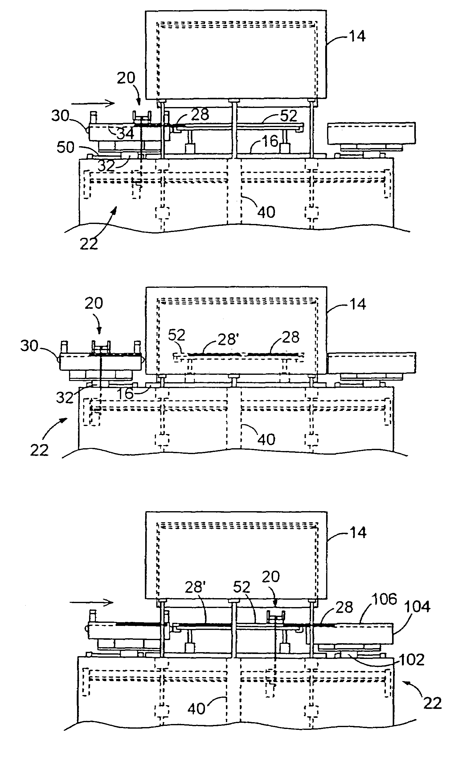
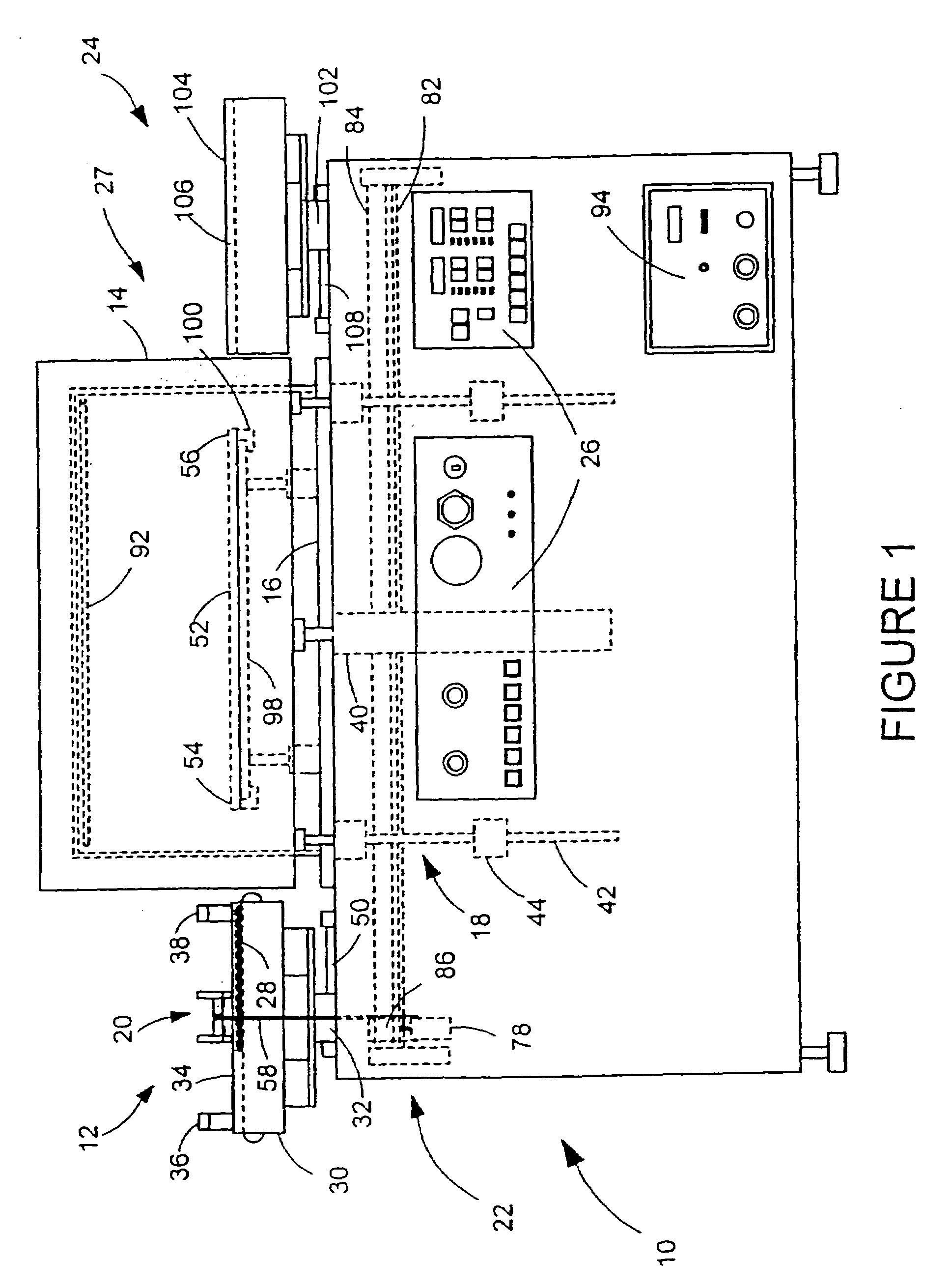
[0058]Referring to the front view of FIG. 1 of the drawings, the plasma treatment system 10 is shown to include the primary components of a conveyor input assembly 12, a reaction chamber 14 and chamber base 16, a chamber lifting assembly 18, a push mechanism 20 and associated linear drive assembly 22, an output assembly 24, an electronic control system 26, and a vacuum and plasma generating system 27. In the particular preferred embodiment 10 shown, printed circuit boards (PC boards) 28 are the electronic parts that are to undergo plasma reaction treatment, although it is to be understood that many other varieties of substrate objects may be substituted.

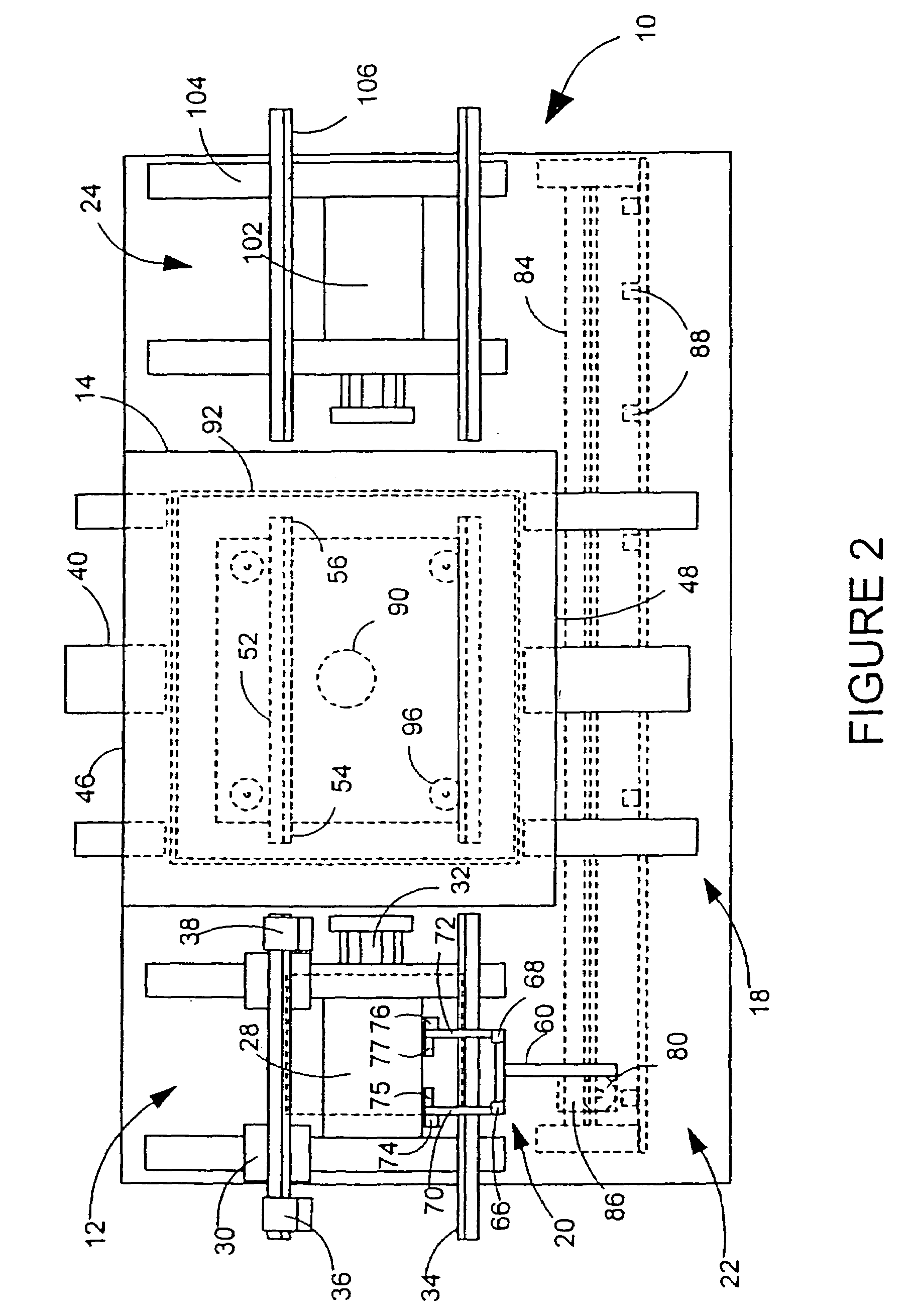
[0059]Referring now to both FIG. 1 and to the top plan view of FIG. 2, the conveyor input assembly 12 utilizes a number of different positioning and movement elements to assist in the transport of the PC boards 28 to the reaction chamber 14. Among these elements are a conveyor 30 and a conveyor position actuator 32, upon which the co...

embodiment 410

[0071]As shown in FIG. 8, the multi-level embodiment 410 incorporates a linear drive assembly 422 as before, but a push mechanism 420 now includes first and second catch assemblies 462 and 464 having first and second catch actuators 466 and 468 which are attached not only to first and second lower catch fingers 470 and 472 (not shown) but to first and second upper catch fingers 124 and 126 (see FIG. 7) as well. The lengths of the catch fingers (470, 472, 124, and 126) are again such as to extend over the travel areas of the PC boards 28. In operation, and referring now to FIGS. 6 and 9a, and also to the end view of FIG. 10, a first catch sensor 475 present on the push mechanism 420 locates the PC board 28 as before. The first catch actuator 466 then lowers the first lower catch finger 470 such that a first catch block 474 may abut and push the PC board 28 when the linear drive assembly 422 is activated. The push mechanism 420 moves the PC board 28 onto the upper input guide rails 11...

third embodiment

[0084]If used in a batch-processing manner, the magazines can be used with a variety of reaction chamber configurations, which have been fitted with vertical electrodes and DC biasing circuitry, as previously described. FIG. 13 shows a plasma treatment system 610, which can be used in manual batch-processing manner or used with robotic manipulation. A plasma treatment system 610 is shown, having an enclosure 612 surrounding a reaction chamber 614. A ground shelf 520 and a powered shelf 510 are shown having attached vertical electrodes 598. Magazines 620 filled with parts to be treated are shown seated on an adjustable shelf 622. The sides (not shown) of the magazines are either open or have slots fashioned to allow plasma flow to reach the parts. A DC bias applied to the powered and ground shelves serves to direct plasma flow through the magazine side slots or open sides to allow uniform treatment, in the manner previously described. The DC and RF power is input to the powered shelv...


PUM

PropertyMeasurementUnit
wettabilityaaaaaaaaaa
strengthaaaaaaaaaa
adhesionaaaaaaaaaa

Abstract

A method for the plasma treatment of parts. The method includes sending loading signals from an electronic control to a transfer mechanism and loading the parts from a position outside of the treatment chamber to a plurality of treatment positions within the treatment chamber based on the loading signals. A plasma is generated within the treatment chamber to treat the parts. After treatment, unloading signals are sent from the electronic control to the transfer mechanism and the parts are unloaded from the treatment chamber based on the unloading signals. Each of the parts may be guided to a corresponding one of the treatment positions during loading.

Description

CROSS-REFERENCE TO RELATED APPLICATIONS[0001]This application is a divisional of U.S. application Ser. No. 09 / 829,305, filed Apr. 9, 2001, now U.S. Pat. No. 6,808,592, which is a continuation of U.S. application Ser. No. 09 / 012,743, filed Jan. 23, 1998, now U.S. Pat. No. 6,245,189, which is a continuation-in-part of U.S. application Ser. No. 08 / 601,687, filed Feb. 15, 1996 (abandoned), and a continuation-in-part of application Ser. No. 08 / 567,797, filed Dec. 5, 1995, now U.S. Pat. No. 5,766,404, which is a continuation-in-part of application Ser. No. 08 / 350,320, filed Dec. 5, 1994 (abandoned).TECHNICAL FIELD[0002]The present invention relates generally to apparatus for plasma treatment, and more particularly to a plasma treatment system that offers an improved automated processing capability.BACKGROUND ART[0003]Gas plasma treatment of a variety of substrates, particularly those in the electronics field, is a well-established and proven process that increases surface activation (wett...

Claims


Application Information

Patent Timeline
Patent Type & Authority Patents(United States)
IPC IPC(8): C23F1/00C23C16/00H01L21/306H01L21/677
CPCH01J37/32082H01L21/67069H01L21/67751H01L21/67772H01L21/67778H01L21/67781H01L2224/85013H01L2924/01078Y10S414/139
Inventor RIGALI, LOUIS A.HOFFMAN, DAVID E.WANG, KEDASMITH, III, WILLIAM F.
Owner NORDSON CORP
Why Eureka
Try Eureka