Oxygen storage material, process for its preparation and its application in a catalyst

a technology of oxygen storage material and catalyst, which is applied in the direction of physical/chemical process catalyst, separation process, lanthanide oxide/hydroxide, etc., can solve the problems of reducing catalyst purification activity, reducing surface area as well as oxygen storage capacity, and using alkaline hydroxides, etc., to achieve the effect of superior oxygen storage material

Inactive Publication Date: 2007-04-10
UMICORE AG & CO KG
View PDF31 Cites 17 Cited by
  • Summary
  • Abstract
  • Description
  • Claims
  • Application Information

AI Technical Summary

Benefits of technology

[0016]Therefore, in a first aspect of the invention, an oxygen storage material comprising cerium oxide and at least one second oxide of a metal M1 selected from the group consisting of alkaline earth metal, rare earth metal, zirconium, zinc, cobalt, copper and manganese wherein cerium oxide and the second metal oxide form Ce / M1 mixed oxide particles is provided. This material shows an unprecedented high oxygen storage capacity and excellent dynamic properties with respect to oxygen storage and release compared to conventional materials.
[0017]The oxygen storage material of the first aspect of the invention can be further stabilized against thermal sintering by doping or coating with an additional oxide of a metal M2, e.g. alumina, or any other thermally stable metal oxide.

Problems solved by technology

Under these severe conditions the primary particles of the oxygen storing materials usually tend to sinter to form larger agglomerates that lead to a loss of surface area as well as oxygen storage capacity, and thus result in a decrease of catalyst purifying activity.
One substantial disadvantage of the described process is the use of alkaline hydroxides, which cannot be completely removed from the product.

Method used


Image

  • Oxygen storage material, process for its preparation and its application in a catalyst
  • Oxygen storage material, process for its preparation and its application in a catalyst
  • Oxygen storage material, process for its preparation and its application in a catalyst

Examples


examples

[0074]The freshly prepared oxygen storage materials were used to determine the specific surface area (SBET), crystallite diameter and inhomogeneity. Then, they were subjected to a TRP-measurement to determine the oxygen storage capacity, ignition temperature Tign. and width of TPR-curve. The obtained data are listed in Table 1.

[0075]In addition, the materials were subjected to an aging treatment for 4 hours at 650° C. in air. After aging the specific surface area was determined a second time. Both surface areas, from the fresh and aged materials, are also listed in Table 1.

reference example r1

[0076]The oxygen storage material used as reference example R1 is a commercial Ce0,63 / Zr0,37-mixed oxide calcined at 400° C. for 4 hours.

Reference Example R2: (CeO2)

[0077]In this example a pure cerium oxide was produced according to the process of this invention for comparison purposes.

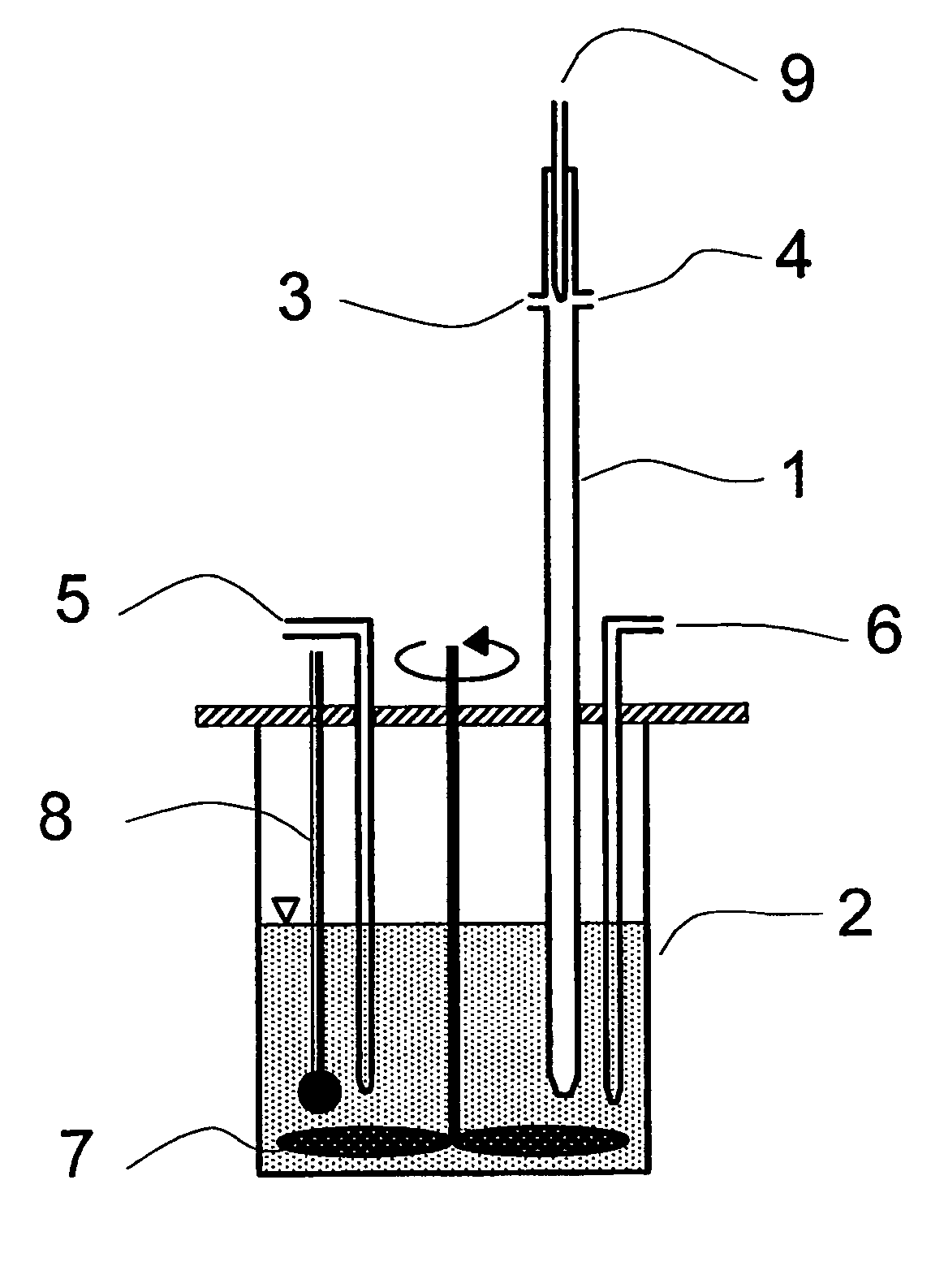
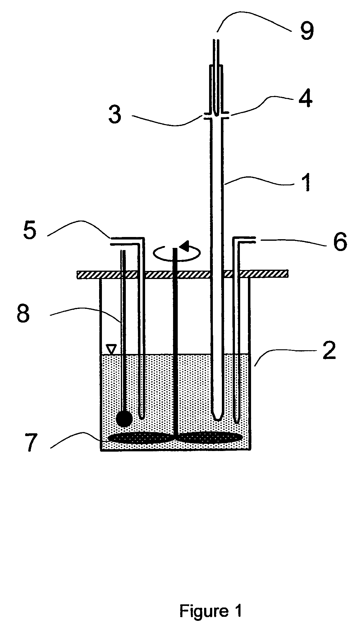
[0078]An aqueous solution of 1.0 mol / l cerium (III) nitrate hexahydrate and an aqueous solution of 0.3 mol / l ammonium oxalate in the desired molar ratio was pumped with constant flow rates into the tubular flow reactor. Turbulent flow was achieved by blowing nitrogen gas in the reactor in flow direction. The combined solutions were added slowly to the hydrolysis reactor under constant pH conditions (pH=4 to 5). The pH value was kept constant by adding the required amount of nitric acid or ammonia, respectively. The resulting precipitate was allowed to reach equilibrium with the hydrolyzing solution during one hour of stirring after which the precipitate was filtered off, washed twice with an aqueous s...


PUM

PropertyMeasurementUnit
temperatureaaaaaaaaaa
temperaturesaaaaaaaaaa
temperatureaaaaaaaaaa

Abstract

An oxygen storage material comprising cerium oxide and at least one second oxide of a metal M1 is disclosed as well as a process for manufacturing the material and the use of this material in an exhaust gas cleaning catalyst. In a preferred embodiment the oxygen storage material comprises particles from a Ce / M1 mixed oxide solid solution coated with an oxide of another metal M2. Metal M1 e.g. can be calcium or zirconium while metal M2 most preferably is aluminum.

Description

CROSS REFERENCE TO RELATED APPLICATIONS[0001]This application is a continuation of U.S. patent application Ser. No. 10 / 389,834, filed Mar. 17, 2003, now abandoned which application is incorporated herein by reference.FIELD OF THE INVENTION[0002]The present invention relates to an oxygen storage material (OSC) on the basis of cerium oxide, a process for producing the same and its application in a catalyst for exhaust gas aftertreatment. The oxygen storage material of the present invention contains cerium oxide, at least one second metal oxide and, preferably, a further metal oxide. The oxides have a very fine particle size, a high resistance against sintering and a high oxygen storage and release capacity.[0003]The oxygen storage materials of the present invention can be employed as a catalyst or catalyst component for purifying exhaust gases of internal combustion engines, especially of stoichiometrically operated otto engines. The catalyst according to the present invention shows e...

Claims


Application Information

Patent Timeline
Patent Type & Authority Patents(United States)
IPC IPC(8): B01J23/00B01J23/10C01F17/235
CPCB01D53/945B01J23/002B01J23/10B01J37/03B82Y30/00C01B13/0262C01B13/0281C01F17/0018C01F17/0043C01G25/00C01G25/006B01D2255/206B01D2255/908B01J2523/00C01P2002/50C01P2002/60C01P2004/64C01P2006/12B01J2523/23B01J2523/3712B01J2523/31B01J2523/48B01J2523/3706Y02T10/22C01F17/32Y02T10/12C01F17/235
Inventor MUHAMMED, MAMOUNADAMOPOULOS, OTHANBOG, TASSILOMUSSMANN, LOTHARLINDNER, DIETERVOTSMEIER, MARTINFEGER, MATTHIASLOX, EGBERTKREUZER, THOMAS
Owner UMICORE AG & CO KG
Why Eureka
Try Eureka