Scanning microscopic method having high axial resolution

a microscopic method and high axial resolution technology, applied in the field of scanning microscopic methods with high axial resolution, can solve the problems of inability to operate the autofocus system during the actual measurement of the sample, adversely affecting the object's registration and characterization, and extremely time-consuming procedures, and achieve high axial resolution and reliable detection.

Inactive Publication Date: 2007-04-10
EVOTEC BIOSYST
View PDF29 Cites 36 Cited by
  • Summary
  • Abstract
  • Description
  • Claims
  • Application Information

AI Technical Summary

Benefits of technology

[0010]Therefore, it is the object of the present invention to provide a method which allows a reliable detection of sheet-like or three-dimensional structures, preferably being a

Problems solved by technology

Thus, in particular when detecting large-surface-structures, there is the problem that during the scanning process it has to be ensured that the focal plane is always situated in a desired position within the objects to be examined.
This adversely effects the object's registration and characterization that has to be performed.
However, it is not the object of said method to track the position of the measuring focus within the s

Method used


Image

  • Scanning microscopic method having high axial resolution
  • Scanning microscopic method having high axial resolution
  • Scanning microscopic method having high axial resolution

Examples


example 1

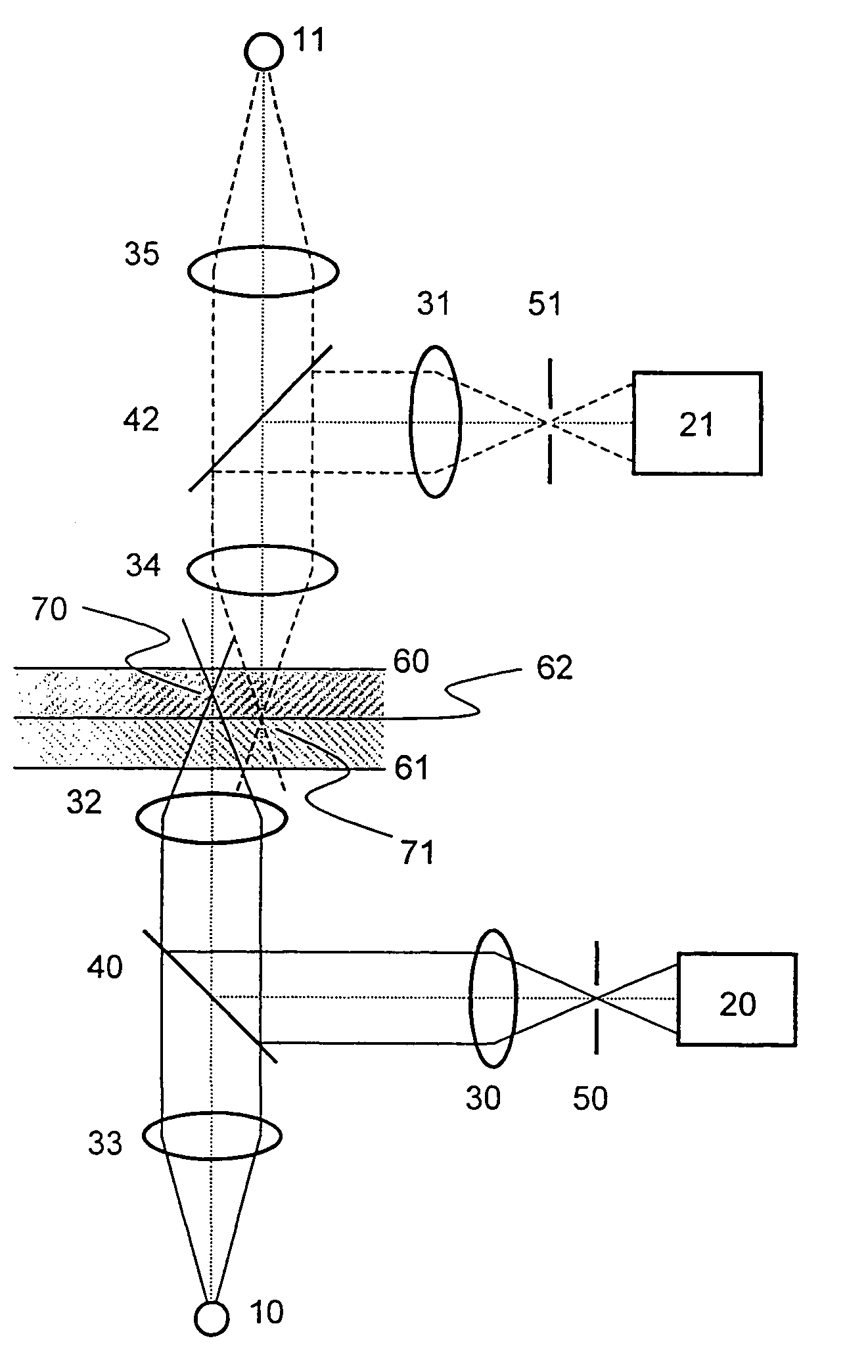
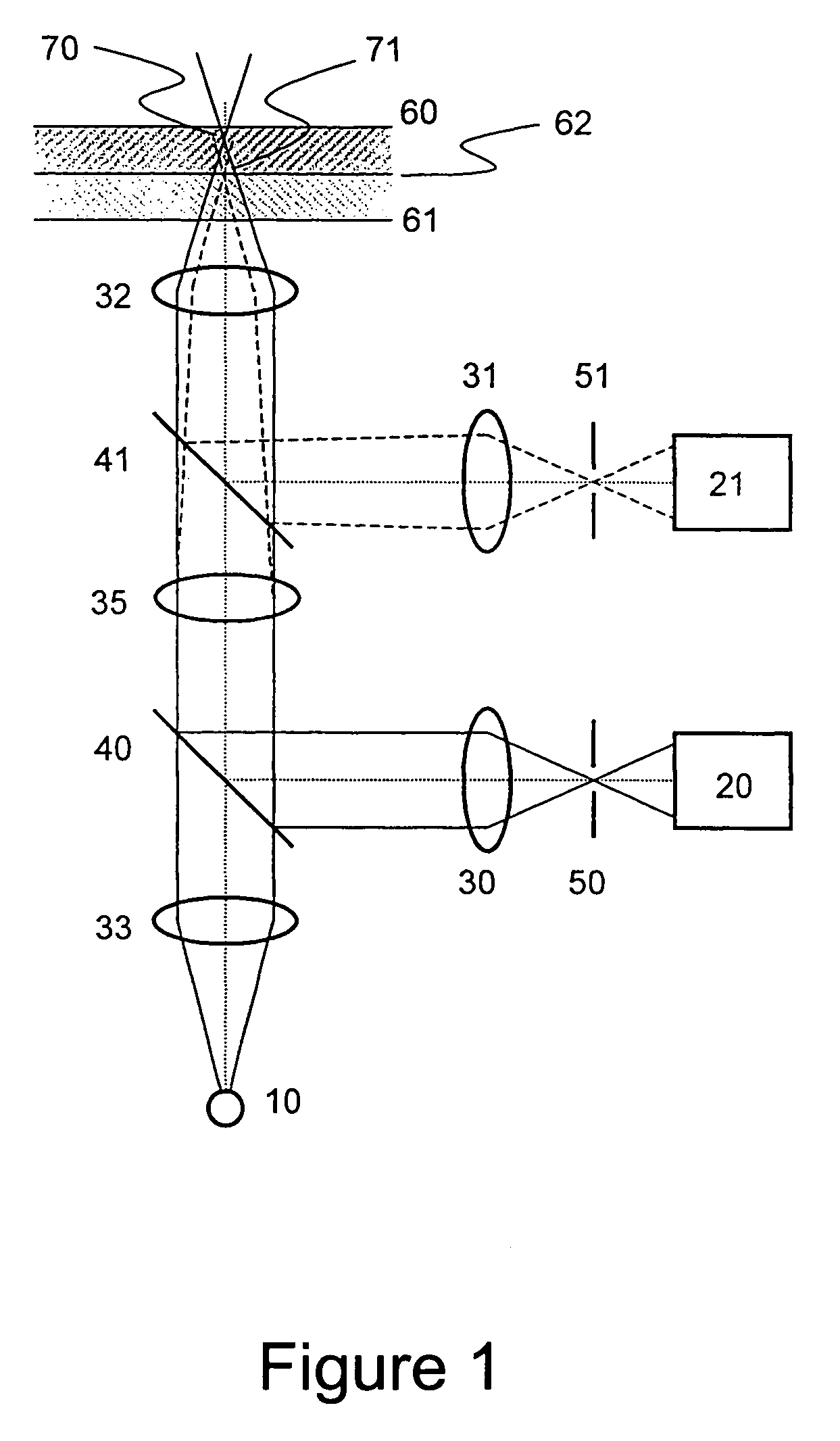
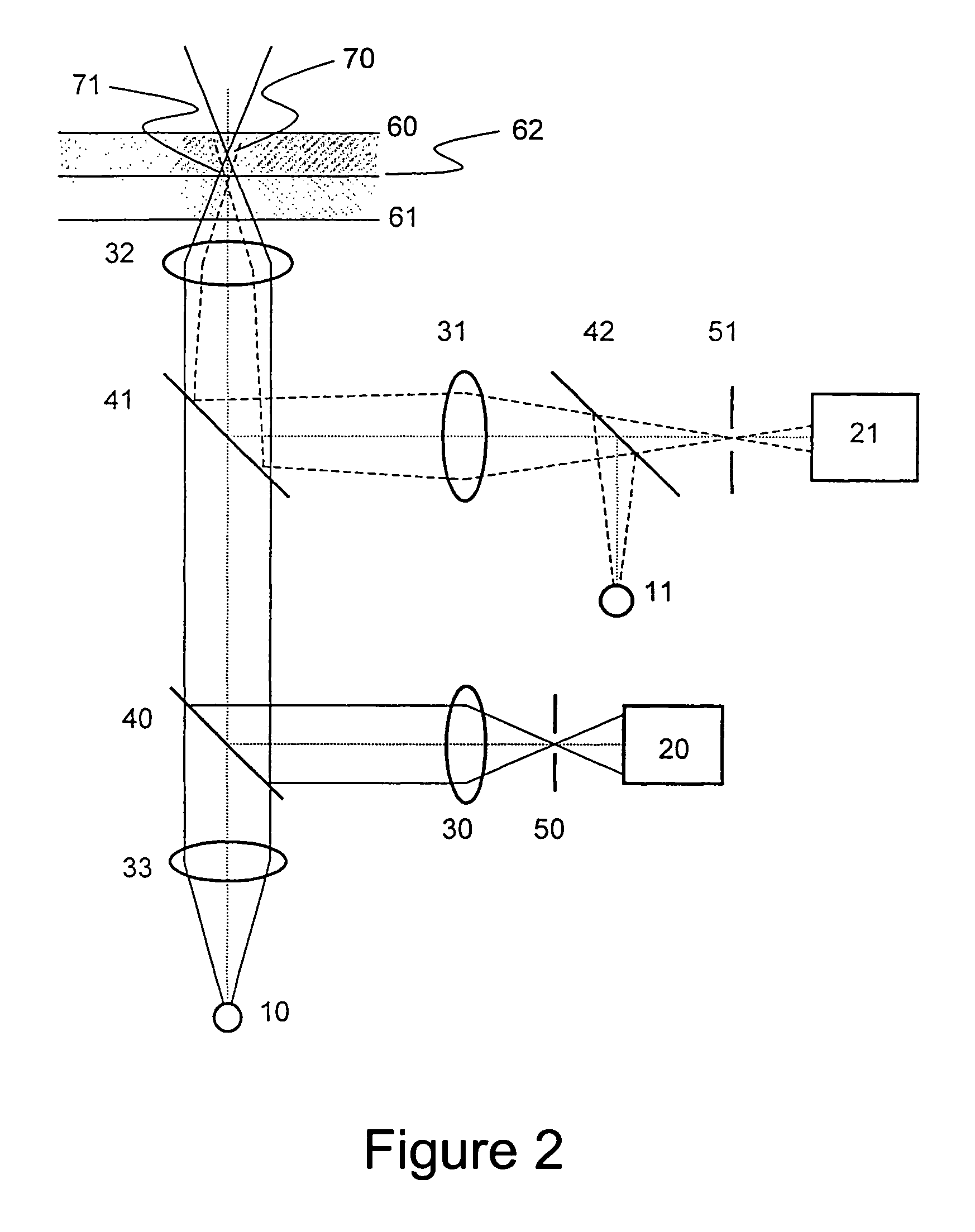
[0061]The present example substantially corresponds to the arrangement shown in FIG. 6. A semiconductor laser 11 having a power of 3 mW and a wavelength of 780 nm is used as radiation source for generating the auxiliary focus 71. The output radiation of the laser 11 is directed to an optical fiber Y-coupling 42 by a monomode-glasfiber 81. Another monomode-glasfiber 80 at the exit of coupling 42 serves for supplying the radiation for the auxiliary focus 72 as well as for confocal detection of the light reflected at the interface 62.

[0062]An achromatic lens 31 having a focus of 40 mm serves for bundling the applied or detected radiation, respectively. The convergence of the ray bundles directed to the objective 32 and thereby the position of the auxiliary focus 71 relative to the measuring volume 70 can be variated by changing the distances between the free end of the fiber 80 and the achromatic lens 31 by lens mover portion 85. In the described embodiment the distance between measuri...

example 2

[0066]In the present example so called tenta-gel™—beads of the type S PHB-Gly (RAPP polymers) are used for the substrate. Those are conjugated with theophylline-molecules (Aldrich) as entities. The charging of the beads is 9%. 5 mg of the beads are suspended in 444 μl PBS-puffers. Lab-tek chambered coverglasses, #1 borosilicate, septic, 8-well (Nunc Nalge International, Lot. No. 148116-0605) are used as sample supports. A polyclonal rabbit anti-theopyllin-antibody (Europa Research, Lot. No. 80 17 15) is used as first antibody. A fluorescently marked (TRITC, Tetra-methylrhodamine-5-(and 6)-isothiocyanate) anti-rabbit-IgG-antibody (DAKO, Lot. No. 077(101)) serves as second antibody. The assay buffer, called TNT in the following, consists of: 50 mM Tris-HCl pH 7,5, 100 mM NaCl, 0,01% Tween-20.

[0067]The assay is done as follows: 8 μl bead suspension are mixed with 100 μl of a 1:2000 dilution of the first antibody and shaken for 30 minutes at room temperature. After that, the twice repea...


PUM


Abstract

The invention relates to a method for optically detecting at least one entity which is arranged on a substrate. The at least one entity is scanned with a measuring volume using at least one radiation source and a confocal optic. During a scanning process an auxiliary focus is generated by means of at least one second radiation source and a second optic. Radiation generated by the first radiation source is collimated by a first optic and radiation generated by the second radiation source is collimated by a second optic. A retroreflection from the auxiliary focus is detected by at least one detector and is used to measuring the position of an interface and, thus, for indirectly positioning the measuring volume. The position of the auxiliary focus relative to the measuring volume is adjustable in a defined manner.

Description

[0001]This application is the national phase under 35 U.S.C. § 371 of PCT International Application No. PCT / EP99 / 10142 which has an International filing date of Dec. 20, 1999, which designated the United States of America and was published in English.BACKGROUND OF THE INVENTION[0002]1. Field of the Invention[0003]The present invention relates to a method for optically detecting at least one entity on or in a substrate, preferably arranged on a support. Furthermore, fields of application of the method according to the invention as well as a device for carrying out said method are described.[0004]2. Description of Related Art[0005]It is known that confocal arrangements or arrangements being constructed for multi-photons-excitation due to their high axial local-resolution are suitable for reduction of background signals which are outside of the focal plane. Thus, in particular when detecting large-surface-structures, there is the problem that during the scanning process it has to be en...

Claims


Application Information

Patent Timeline
IPC IPC(8): G01N21/55F21V9/16G01B11/14G01J1/58G01J3/30G01J3/44G01J4/00G01N21/00G01T1/10G02B27/40G02B27/64G02B7/04G21H3/02G21K5/00H01J65/06H01J65/08G01B11/24G01J3/02G01N21/17G01N21/47G01N21/64G01N21/65G01N33/483G02B21/00
CPCG01J3/02G01J3/0237G01N21/6458G02B21/008G02B21/006G02B21/0068G02B21/0076G01N21/6408G01N21/6445G01N2021/6439G01N21/65
Inventor MUELLER, JUERGEN ROLFHENCO, KARSTENTURNER, RODNEYAXHAUSEN, PETERGUENTHER, ROLF
Owner EVOTEC BIOSYST
Why Eureka
Try Eureka