Structural element with rib-receiving member

a technology of structural elements and ribs, applied in the direction of electrical generators, transportation and packaging, mechanical equipment, etc., can solve the problems of high cost of use of honeycomb materials, high maintenance and repair costs, and high cost of life cycle, so as to reduce the number of parts and eliminate the extensive assembly tooling. , the effect of high strength

Inactive Publication Date: 2007-04-17
ROHR INC
View PDF13 Cites 39 Cited by
  • Summary
  • Abstract
  • Description
  • Claims
  • Application Information

AI Technical Summary

Benefits of technology

[0095]The structural element according to the present invention permits the elimination of extensive assembly tooling and reduced part count. The structural element of this invention also provides high strength, low weight, and improved stiffness.
[0096]Unlike honeycomb structures, the structural element of this invention does not comprise small cellular areas that can trap moisture. In fact, the structure lends itself to direct venting and drainage systems to elimina

Problems solved by technology

Depending on the particular application, the use of such honeycomb material may be expensive, in terms of life cycle costs, and may require extensive maintenance and repair.
In some circumstances, it is also not readily adaptable to the attachment of other components.
This drawback may be overcome by reinforcing elements within the honeycomb, but this typically involves adding to the weight of the structural element and thus reducing the advantage of the low weight of the honeycomb material.
Furthermore, honeycomb core structures suffer from susceptibility to moisture intrusion resulting from thei

Method used


Image

  • Structural element with rib-receiving member
  • Structural element with rib-receiving member
  • Structural element with rib-receiving member

Examples


Embodiment Construction

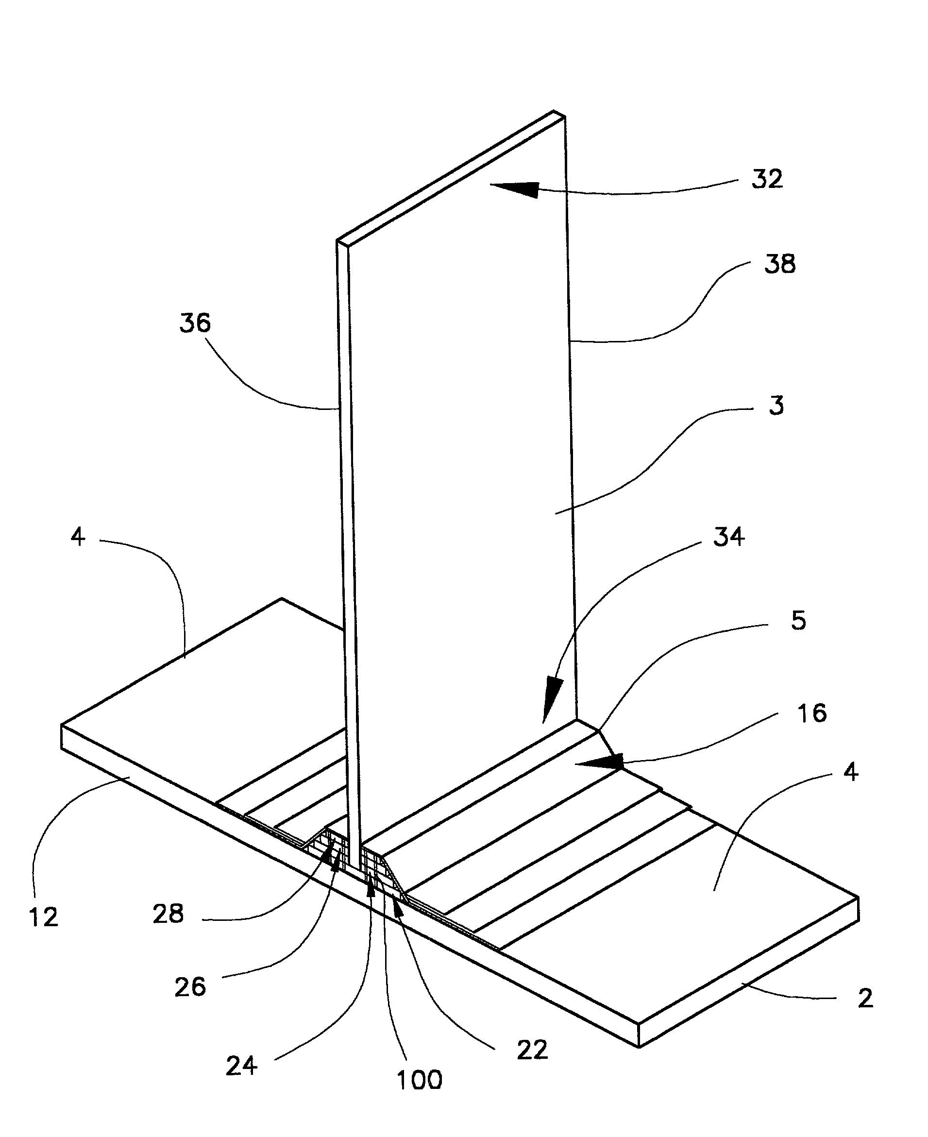
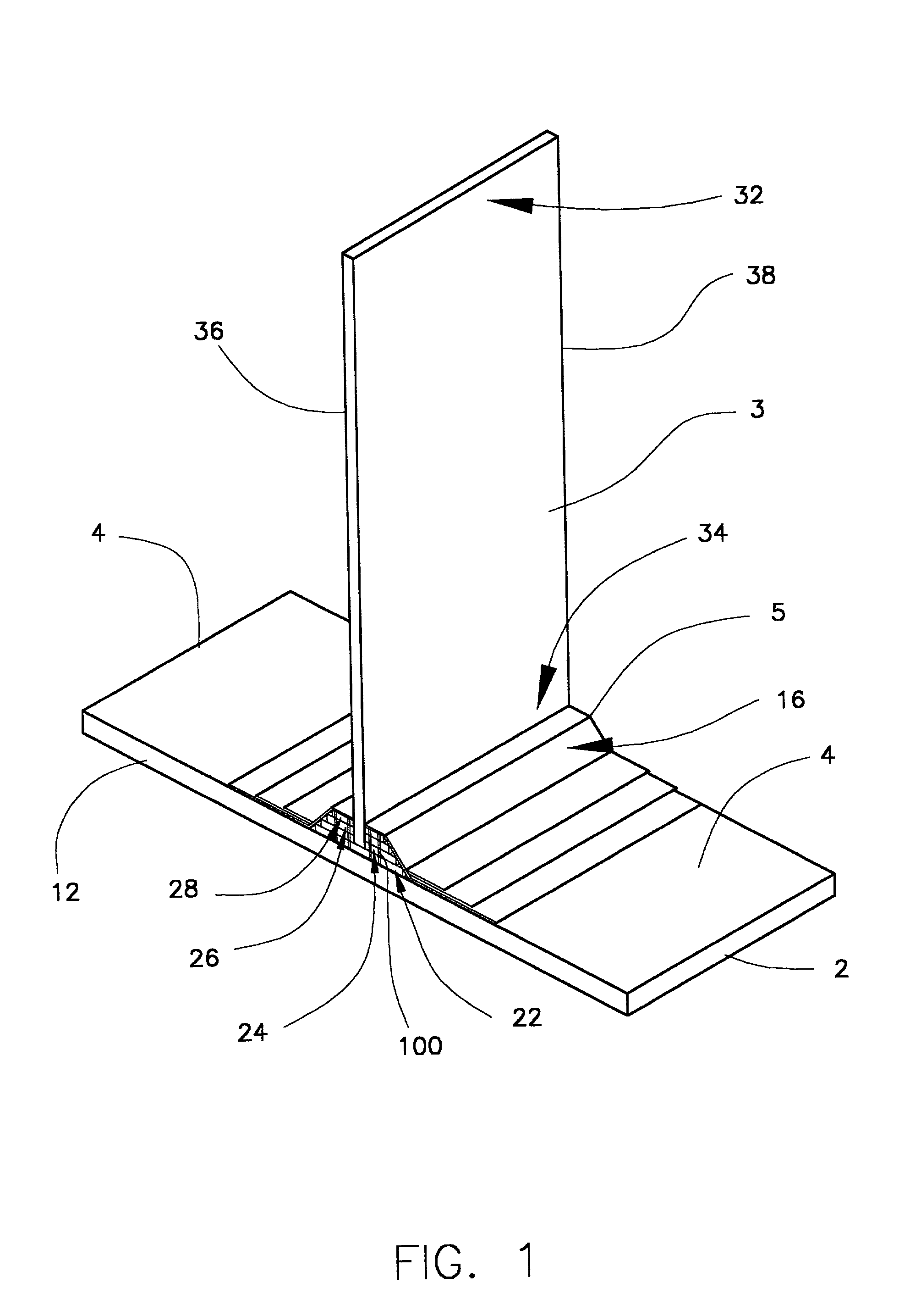
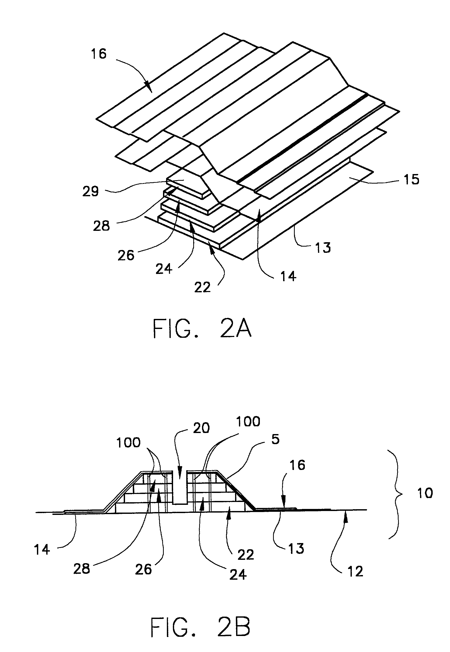
[0105]Various embodiments of this invention are illustrated by reference to FIGS. 1–4 herein. FIG. 1 shows the assembled structural element of one embodiment of this invention. The composite structure comprises: a first member or face sheet 12 having an inner surface 4 and an outer surface 2; a rib-receiving member 5; a rib member 3 having a first end 34, a second end 32, a first edge 36 and a second edge 38. The first member may be, for example, a face sheet which is employed in an aerospace structure such as an aircraft wing or an internal aerospace structure such as a strut or the like. The first member may be fabricated from metal or a composite material, but is preferably fabricated from a composite material, as is further described herein. A second member (not shown) which is similar to the first member may receive second end 32 of rib member 3 by using a second rib-receiving member, as shown, for example, in FIGS. 5A and 5B. Rib-receiving member 5 comprises at least one cover...


PUM

PropertyMeasurementUnit
Widthaaaaaaaaaa

Abstract

A structural element for use in aerospace applications such as a structural element suitable as an aircraft component is described. In one embodiment of the invention, the composite structure comprises: (a) at least one member having an inner surface and an outer surface; (b) a rib having a first end and a second end; (c) a rib-receiving member integral to the inner surface of the at least one member, wherein the rib-receiving member comprises a plurality of rib-receiving elements and openings therein for receiving the first end of the rib and at least one cover sheet having an opening therein for receiving the first end of the rib; and (d) at least one anchoring element interconnecting the rib-receiving elements. In another embodiment of the invention, the composite structure comprises: (a) at least one member having an inner surface and an outer surface; (b) a rib having a first end and a second end; and (c) a rib-receiving member integral to the inner surface of the at least one member, wherein the rib-receiving member comprises a rib-receiving sleeve having an open end for receiving the rib and a closed end, and two sleeve support members, wherein the sleeve support members are disposed on opposite sides of the sleeve and interconnect the sleeve to the inner face of the at least one member.

Description

BACKGROUND OF THE INVENTION[0001]1. Field of the Invention[0002]This invention relates to a structural element useful in aerospace applications, as well as a method of preparing such a structural element for use in aerospace applications, such as a structural element suitable as an aircraft component. In particular, in the present invention the structural element comprises a first member such as a face sheet, and at least one rib-receiving member integral to the first member, wherein the rib-receiving member comprises either: (i) a plurality of rib-receiving elements for receiving the rib member with at least one anchoring element interconnecting the rib-receiving elements; or (ii) a rib-receiving sleeve for receiving the rib member.[0003]2. Background Information[0004]Aircraft components including intake ducts, flooring and wing sections are often made of honeycomb material which is lightweight, rigid and capable of being fabricated in many shapes. Depending on the particular appli...

Claims


Application Information

Patent Timeline
IPC IPC(8): B32B7/00B64C1/00B64C7/00B64C25/16
CPCB64C1/064B64C2001/0072B64C2001/0081Y02T50/433Y10T428/17Y10T428/2457Y10T428/24537Y10T428/24182Y10T428/24322Y10T428/24289B29C65/48B29C66/43441B29C66/721Y02T50/40
Inventor HAMMI, BASILHUBERT, CLAUDE
Owner ROHR INC
Why Eureka
Try Eureka