
Method for operating a direct injection diesel engine

a diesel engine and direct injection technology, applied in the direction of machines/engines, output power, electric control, etc., can solve the problems of increased particulate burning, loss of efficiency, and reduction of maximum temperatur

Active Publication Date: 2007-04-24
AVL LIST GMBH
View PDF17 Cites 17 Cited by
  • Summary
  • Abstract
  • Description
  • Claims
  • Application Information

AI Technical Summary

Benefits of technology

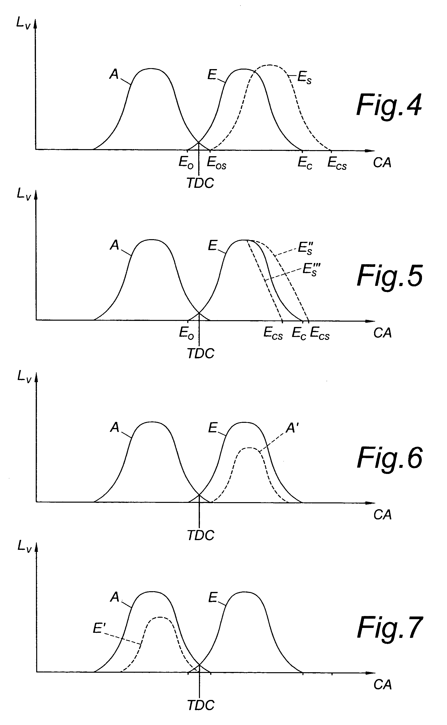
The present invention relates to a method for operating an internal combustion engine that can achieve low nitrogen oxide and particulate emission levels while maintaining high efficiency over the whole load range. The method involves starting fuel injection in a second operating region, which occurs after top dead center and before 20° crank angle after top dead center. This second operating region is characterized by relatively high exhaust gas recirculation rates and low temperatures. The method also involves using multiple injection beings and variable intake valve closing time to optimize engine performance. The invention can be applied to both direct injection diesel engines and reciprocating piston engines.

Problems solved by technology

It is disadvantageous that especially in the medium load region a low air ratio combines with low combustion temperature and thus efficiency is lost.
The back-shifting of the combustion process causes a reduction of maximum temperature, but at the same time leads to an increase of mean temperature at a certain later crank angle, which results in an increased burning of particulates.
A disadvantage of the method is again low efficiency at low load.

Method used


Image

  • Method for operating a direct injection diesel engine
  • Method for operating a direct injection diesel engine
  • Method for operating a direct injection diesel engine

Examples


Embodiment Construction

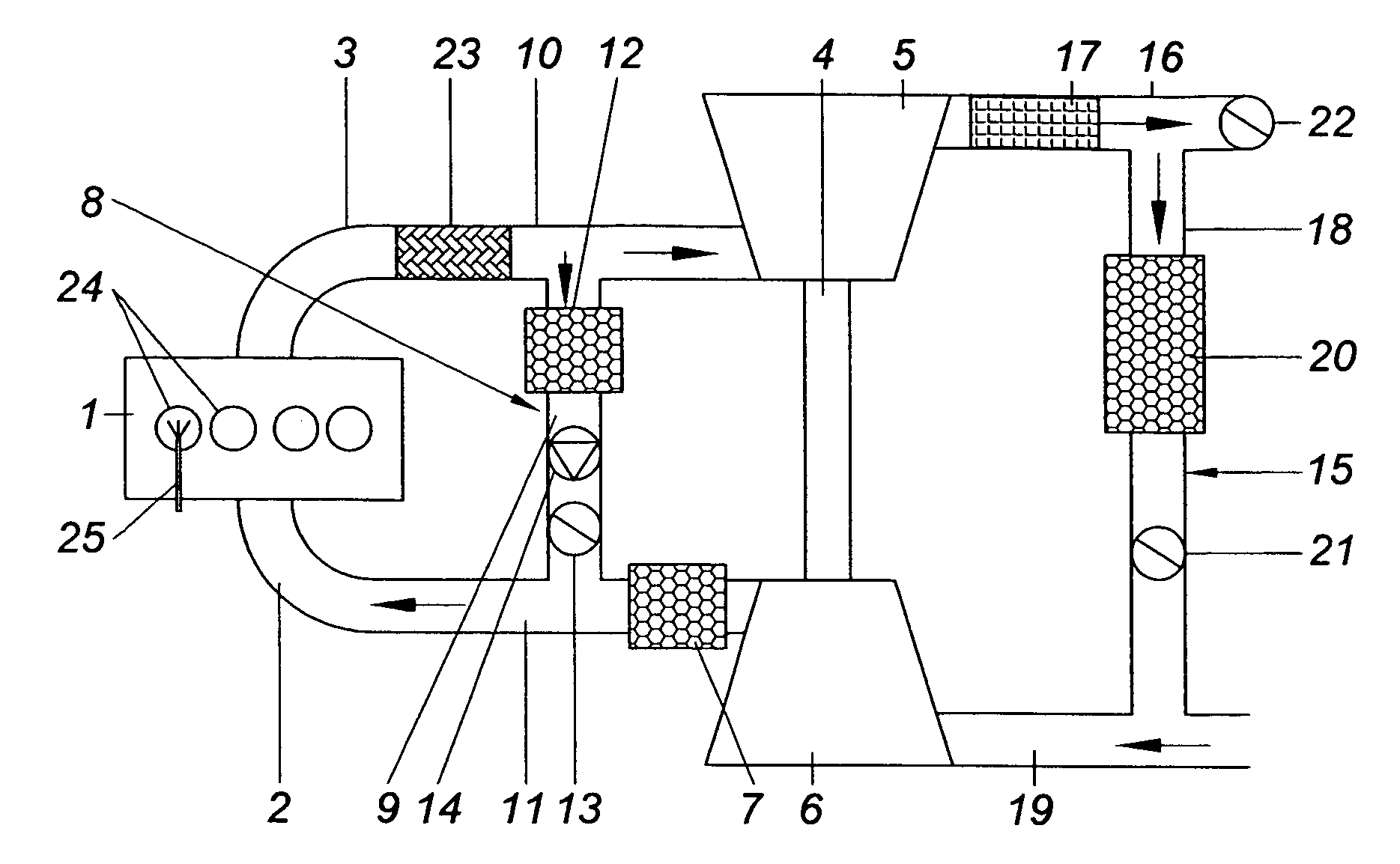
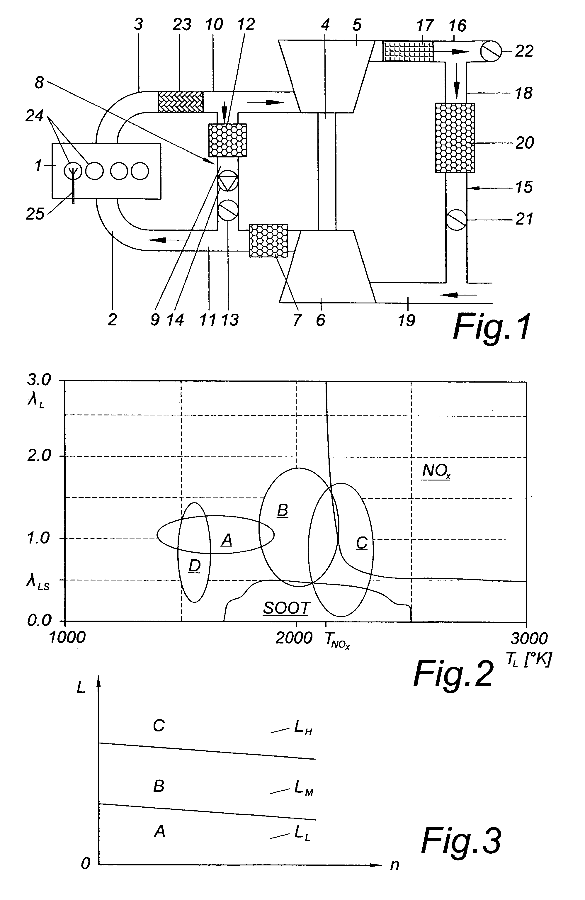
[0030]FIG. 1 shows an internal combustion engine 1 with an intake manifold 2 and an exhaust manifold 3. The internal combustion engine 1 is charged by an exhaust gas turbocharger 4 comprising an exhaust-gas-driven turbine 5 and a compressor 6 driven by the turbine 5. On the intake side an intercooler 7 is placed following the compressor 6 in flow-direction.

[0031]Furthermore a high-pressure exhaust gas recirculation system (EGR-system) 8 with a first exhaust gas recirculation line 9 is provided between the exhaust gas line 10 and the intake line 11. The EGR-system 8 comprises an EGR-cooler 12 and an EGR-valve 13. Depending on the pressure difference between the exhaust line 10 and the intake line 11 an exhaust gas pump 14 may be provided in the EGR-line 9 in order increase or to control the EGR-rate.

[0032]In addition to this high-pressure EGR-system 8 a low-pressure EGR-system 15 is provided downstream of the turbine 5 and upstream of the compressor 6, a second EGR-line 18 departing ...


PUM


Abstract

A method for operating a direct injection diesel engine which is operated in a first operating region corresponding to low to medium partial load in such a way that fuel combustion takes place at a local temperature below the temperature of NOx formation and with a local air ratio above the limit value for soot formation, and where fuel injection starts in a range of between 50° to 5° crank angle before top dead center of the compression phase and where exhaust gas is recirculated at an exhaust gas recirculation rate of 50% to 70%. In order to achieve high efficiency in each operating region while keeping NOx and particulate emissions low, in a second operating region corresponding to medium partial load, fuel injection is started in a range from approximately 2° crank angle before top dead center to approximately 20° crank angle after top dead center.

Description

BACKGROUND OF THE INVENTION[0001]The invention relates to a method for operating a direct injection diesel engine which is operated in a first operating region corresponding to low to medium load in such a way that combustion of the fuel takes place at a local temperature below the formation temperature of NOx and with a local air ratio above the ratio at which particulates are formed, where fuel injection is initiated at a crank angle of 50° to 5° before top dead center of the compression phase and where exhaust gas is recirculated at a recirculation rate of 50% to 70%. The invention furthermore relates to an internal combustion engine implementing the method.[0002]The most important variables governing the combustion process in a combustion engine with internal combustion are the phase of the combustion or rather the phase of the start of combustion, the maximum rate of increase of cylinder pressure, and the peak cylinder pressure.[0003]In an internal combustion engine in which co...

Claims


Application Information

Patent Timeline
Patent Type & Authority Patents(United States)
IPC IPC(8): F02B3/00F02M25/07F02B1/12F02B3/06F02D13/02F02D15/00F02D21/08F02D41/00F02D41/02F02D41/04F02D41/30F02D41/38F02D41/40F02D43/00
CPCF02D41/0007F02D41/0057F02D41/3035F02D41/401F01N2340/04F02B1/12F02B3/06F02B2275/14F02D41/006F02D41/0065F02D41/3064F02D2041/001F02D2250/31F02D2250/36Y02T10/44Y02T10/123Y02T10/144Y02T10/47Y02T10/12Y02T10/40
Inventor CHMELA, FRANZCSATO, JANOSGLENSVIG, MICHAELSAMS, THEODOREICHLSEDER, HELMUTFIGER, GUNTERFUCHS, CHRISTIANPIRKER, GERHARDWIMMER, ANDREAS
Owner AVL LIST GMBH
Learn More