
Dual helix active fixation stimulation lead

a technology of active fixation and lead, which is applied in the direction of external electrodes, electrotherapy, therapy, etc., can solve the problems of too low local sensed p-wave signal, too extensive p-wave sensing or variation to be useful, and achieves high electrical efficiency, improved sensing and pacing uniformity, and improved

Active Publication Date: 2007-05-01
PACESETTER INC
View PDF11 Cites 94 Cited by
  • Summary
  • Abstract
  • Description
  • Claims
  • Application Information

AI Technical Summary

Benefits of technology

[0009]As mentioned above, active fixation bipolar cardiac pacing and / or sensing leads typically utilize a helix for the fixation of the lead's distal tip to endocardial tissue, at various sites either in the right ventricle or in the right atrium. One property of such leads is that they commonly use the helix as an active electrode, usually the cathode, whereas the anode electrode is typically ring shaped, typically positioned 8 to 28 mm proximal to the helix tip electrode. Such leads are very commonly used for right atrial pacing and sensing because they are so effective at remaining secure at the site the implanting physician wants. However, such leads can easily also sense far field R-wave signals or other far-field signals. This can also be true for leads positioned in the RV where they can sense FF P-waves or other FF signals. In an effort to reduce the sensed far field signals, efforts have been undertaken to develop a lead which provides for a tip to ring electrode separation of only about 1.1 mm. Such a design can significantly reduce the size of far field signals.
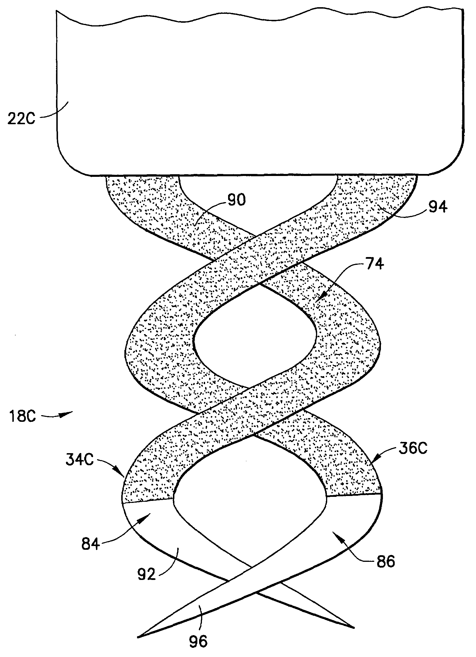
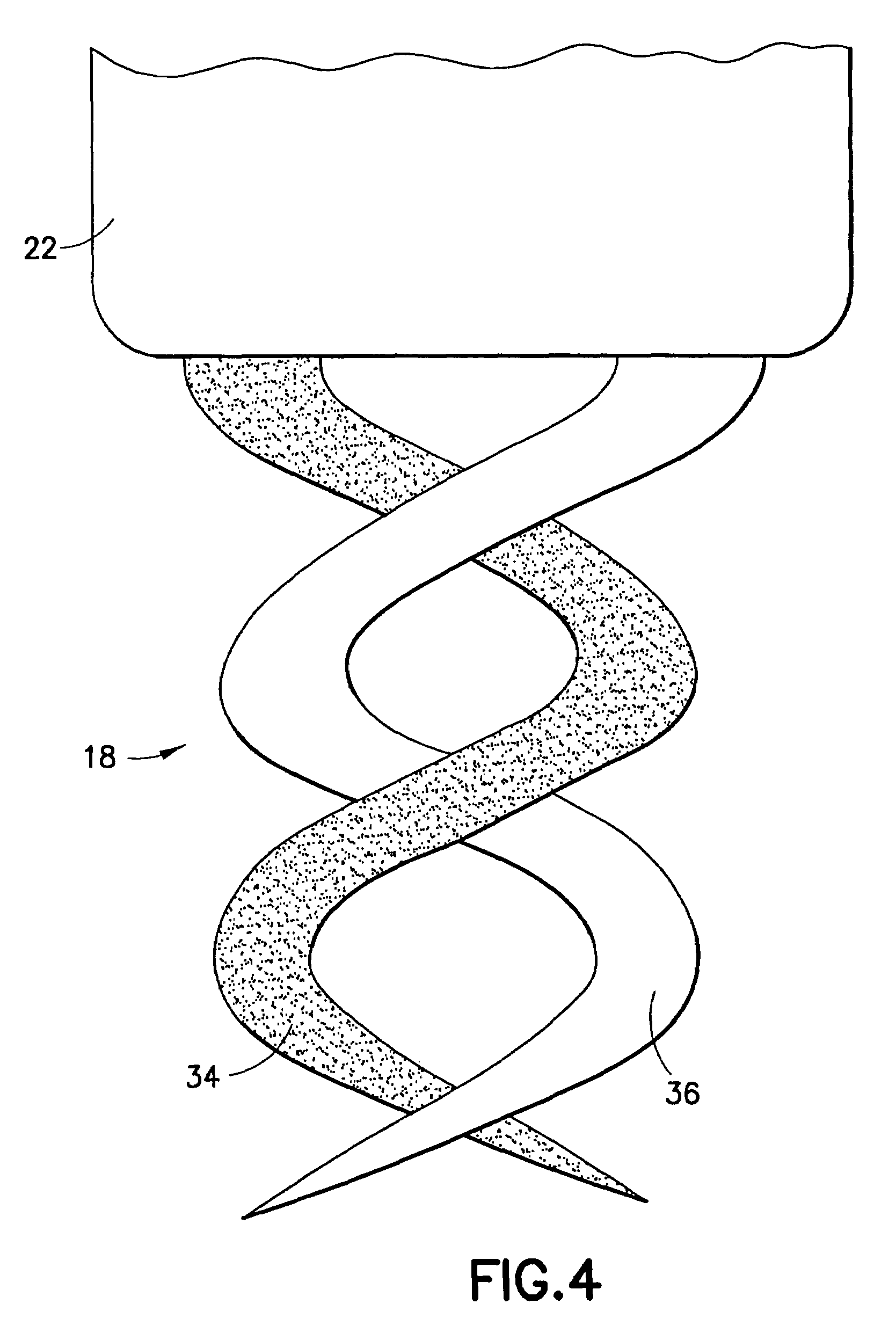
[0011]What is disclosed, then, is a simple apparatus in which a new lead utilizes all the identical design, material, and processing as current state-of-the-art bipolar active fixation leads, except that the lead has no anode ring electrode. Instead, the helix fixation is actually of a dual helix / dual electrode construction, on the same axis, where one helix is the cathode and the other helix is an anode. With this approach, the anode helix can be a fully active helix bearing no insulation (for example, having about a 2 mm extension, with two turns, using 0.012 in diameter wire, and having a surface area of about 8 sq. mm). At the same time, the cathode helix can be identical in physical size to the anode helix, but a portion of it, specifically, the proximal portion, may be insulated so that the active surface area is about 3 or 4 sq. mm. This helix could also have about half of the surface masked-off in a way such that the entire cathode helix has small sections along its length intermittently insulated and un-insulated, creating a “full” length helix but with only about half the active surface area. Such dimensions and designs assure that the typical pacing impedance should always be at least 500 to 600 ohms or higher. Alternatively, various insulation amounts could be selectively used on either the anode helix or the cathode helix at various locations, so as to tailor the pacing impedance and / or sensing and / or stimulation characteristics to achieve various attributes or meet various requirements. The electrode's active surfaces would also utilize highly electrically efficient coatings such as titanium nitride (TiN). Importantly, this design assures that both electrodes are actually embedded in the myocardium. This feature allows for improved, more uniform sensing and pacing.

Problems solved by technology

However, one of the concerns of such a lead is that the anode ring electrode may be positioned in the blood pool and thereby the local sensed P-Wave signal can potentially be attenuated to be too low for the device to effectively use the signals to assist in operating the various algorithms.
Thus, a drawback to this current design approach would be that, in some cases, the sensing of the local P-wave may be too extensively compromised or varied to be useful.

Method used


Image

  • Dual helix active fixation stimulation lead
  • Dual helix active fixation stimulation lead
  • Dual helix active fixation stimulation lead

Examples


Embodiment Construction

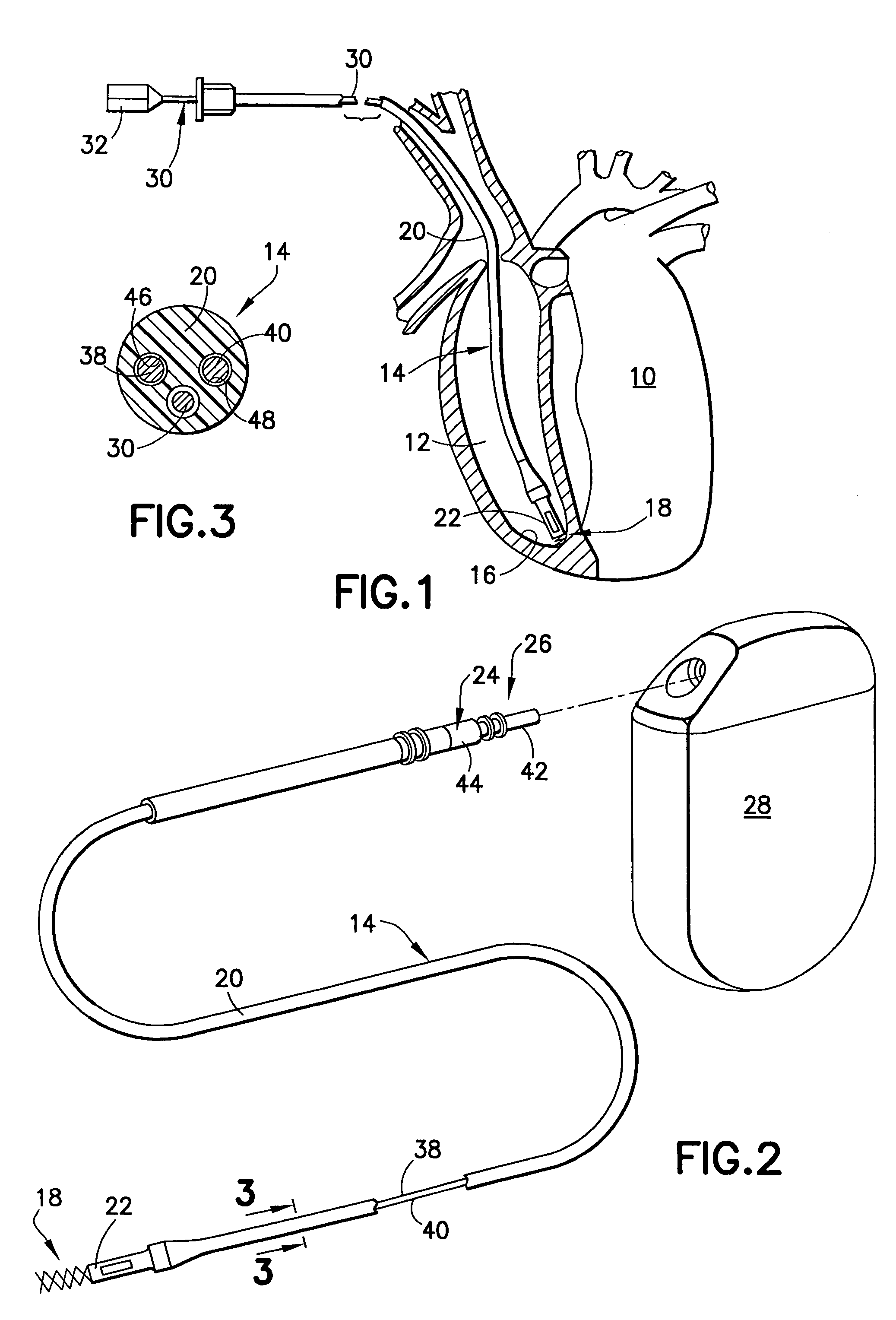
[0025]Referring now to FIG. 1, there is shown a diagrammatic perspective view partially cut away and shown in section of a heart 10 into the right ventricle 12 of which is inserted a body implantable lead 14 of the endocardial type incorporating features of the present invention. Although the present invention will be described with reference to the embodiments shown in the drawings, it should be understood that the present invention can be embodied in many alternate forms or embodiments. In addition, any suitable size, shape or type of elements or materials could be used. The lead 14 of an active fixation design, may be attached to an interior wall 16 of the heart 10 by means of an active fixation helical electrode assembly 18 which is fixated by screwing the helical electrode assembly through the heart's endocardium into the heart's myocardium. It will be understood that such a lead could also be fixated by screwing the helical electrode assembly through the exterior or epicardial...


PUM


Abstract

An implantable lead for use with an implantable medical device includes a lead body with first and second electrical conductors extending between its proximal and distal ends. An electrical connector at the proximal end of the lead body includes terminals electrically connected to the first and second conductors. First and second coaxial active fixation helices are coupled to the lead body's distal end, one being an anode, the other an electrically isolated cathode. Each helix has an outer peripheral surface with alternating insulated and un-insulated portions along its length with about a half of the surface area being insulated. The un-insulated portions of the helices may be formed as a plurality of islands in the insulated portions, or as rings spaced by insulative rings, or as longitudinally extending strips spaced by longitudinally extending insulative strips.

Description

FIELD OF THE INVENTION[0001]The present invention relates generally to implantable leads for medical devices which provide stimulating pulses to selected body tissue, for example, the heart, and more particularly, to an implantable stimulation lead having a bipolar active fixation electrode for pacing and sensing electrical activity in the heart.BACKGROUND OF THE INVENTION[0002]Pacing leads having at least two electrodes adjacent to the distal end are used for bipolar pacing, as well as for providing sensory information to an attached cardiac pacemaker. Generally, bipolar pacing leads are either active or passive fixation, the former using tines typically, and the latter using a screw mechanism. A bipolar active fixation lead can have its helical screw be one of its electrodes and a ring electrode spaced from the distal end of the pacing lead as its second electrode. The spacing between the two electrodes is usually dependent upon the physical constraints attendant with the design o...

Claims


Application Information

Patent Timeline
IPC IPC(8): A61N1/04
CPCA61N1/0573
Inventor HELLAND, JOHN R.
Owner PACESETTER INC
Learn More