Microwave molding of polymers

a technology of micro-wave energy and polymer, which is applied in the direction of auxillary shaping apparatus, manufacturing tools, coatings, etc., can solve the problems of increased thermal gradient, inability to meet the needs of manufacturing, and design that does not provide uniform heating of work materials, etc., to achieve efficient heating of microwave energy, easy mold parts fabrication, and smooth surface finish

Inactive Publication Date: 2007-05-29
AKOPYAN RAZMIK
View PDF57 Cites 10 Cited by
  • Summary
  • Abstract
  • Description
  • Claims
  • Application Information

AI Technical Summary

Benefits of technology

[0018]The present invention comprises a compression mold for use in heating and shaping a polymer work material in a microwave oven. The mold includes a sidewall mold member and a pair of end mold members at least one of which is compressible toward the other to compress a quantity of work material positioned within a mold cavity formed between the mold members. The sidewall mold member comprises a sleeve formed from hard and wear resistant material, capable to withstand high tensile stresses on the order of 50,000 psi and high temperatures around 900° F. Another requirement is that the material of the sleeve has a relatively smooth surface finish. Metals or alloys are suitable materials for the sleeve, which extends around the mold cavity. The sleeve may be of a wide variety of geometries including round, square, rectangular or oval. The metal sleeve preferably defines the inner surface of the mold cavity in which the material to be molded or work material is placed. A layer of microwave absorbing material that will be efficiently heated by microwave energy is formed on the outer surface of the metal sleeve. In this mold design, the electric field will be almost zero on the inner surface of the metal sleeve which defines the peripheral region of the work material. This peripheral region of the work material is not heated directly by microwave energy. Rather the peripheral region of the work material is heated by thermal conduction and radiation through the metal layer from the outer microwave absorbing layer. Such a mold design does not provide uniform heating of the work material by direct absorption of microwave energy, rather it seeks to obtain approximate uniform heating through hybrid heating. The inability to obtain true uniform heating of the work material by direct absorption of microwave energy is well compensated for by the numerous benefits obtained by hydrid heating with metal mold components, including easy of fabrication of the mold parts for even complicated part shapes, the ability to polish the inner mold surfaces thereby maintaining the mold quality, and significantly increased lifetime and reduced costs to manufacture the mold. The employed hybrid heating provides high quality molding and significantly reduces heating time in comparison with conventional compression molding processes.
[0020]In this embodiment, the smallest temperature gradients across the mold structure and, hence, the shortest processing times may be achieved by maintaining approximately equal heating rates of all the mold members and the central region of work material. This may be accomplished by equalizing the effective thermosensitivities of the work material and the material forming each mold member. If the effective thermosensitivity of the work material does not match that of the mold members, it will result in increased thermal gradients and, hence, will require longer processing times.
[0022]The apparatus for compressing the end mold members toward each other is made of microwave transparent materials. The metal sleeve and metal layers on the end mold members are less susceptible to wear than the microwave absorbing material which is typically a ceramic material which is prone to chipping, cracking and wearing. Use of the metal sleeve and metal layers on the end mold members increases the life of the mold due to the high tensile strength of metal and its capability to provide good surface finish of the mold cavity.
[0023]In another embodiment of the present invention thermally conductive spacers or separators are positioned between alternating layers of work material in the mold cavity to form a multi-layer structure. The separators are preferably formed of metal, alloys, ceramic or other materials having relatively high thermal conductivity to promote heat transfer from hot peripheral regions of the mold members or work material into its central region and, thus, to provide relatively uniform and fast heating of this multi-layer structure. In another embodiment the separators are made from microwave absorbing ceramic such as silicone carbide.

Problems solved by technology

Such a mold design does not provide uniform heating of the work material by direct absorption of microwave energy, rather it seeks to obtain approximate uniform heating through hybrid heating.
If the effective thermosensitivity of the work material does not match that of the mold members, it will result in increased thermal gradients and, hence, will require longer processing times.

Method used


Image

  • Microwave molding of polymers
  • Microwave molding of polymers
  • Microwave molding of polymers

Examples


example 1

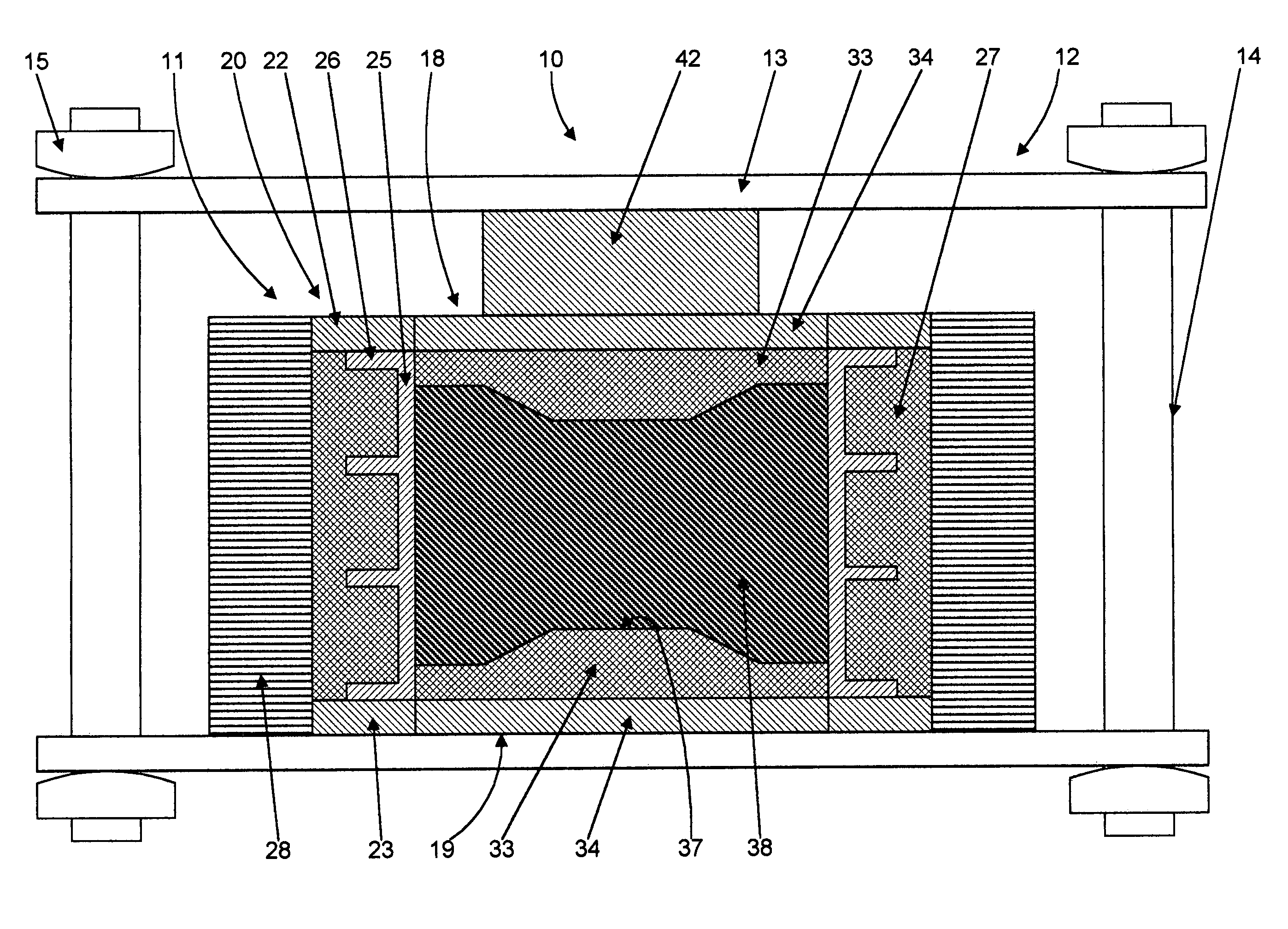
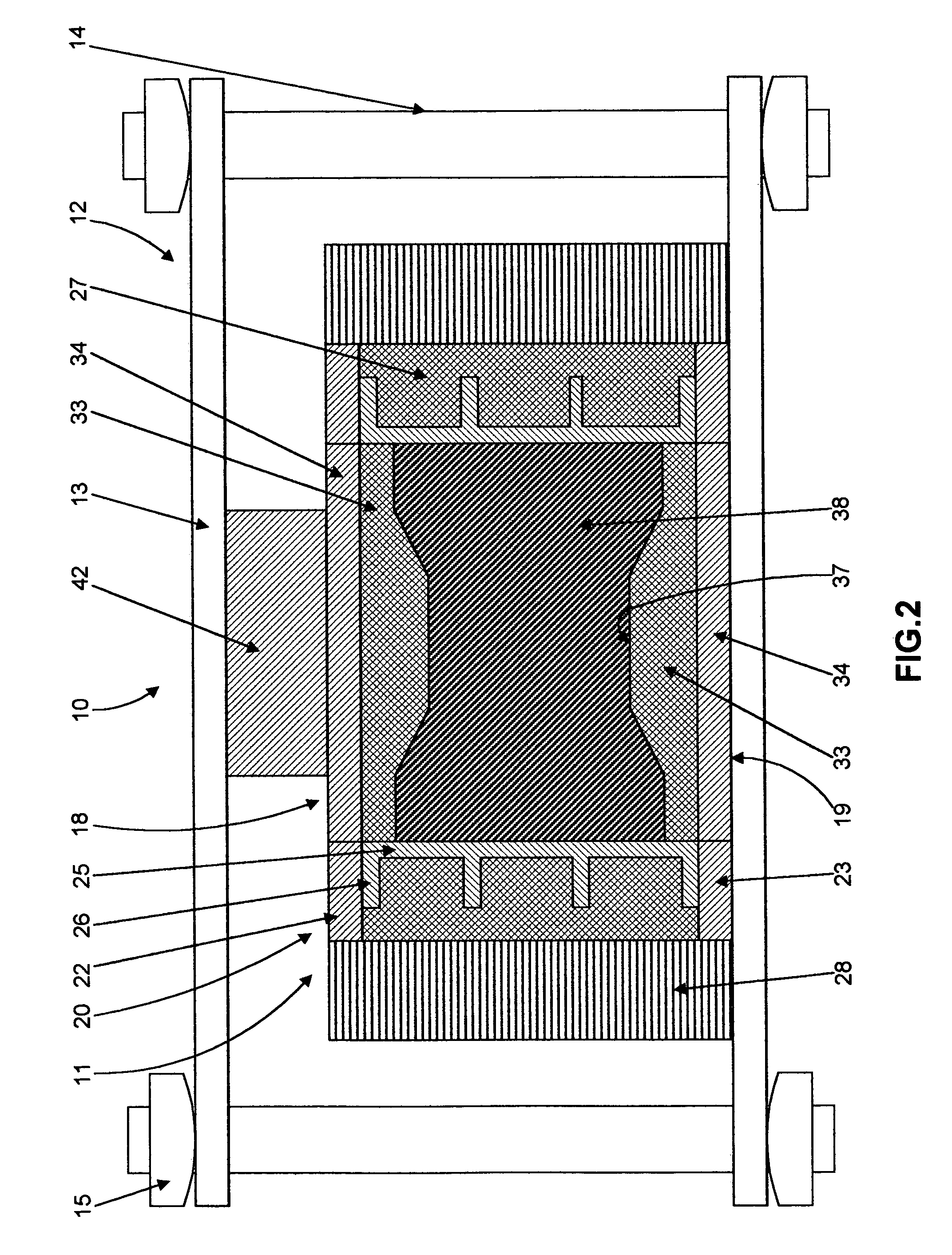
Mold for Parts 5″ in Diameter

[0081]A mold of the type generally shown in FIG. 2 as mold 11 was created for molding a part having a diameter of 5 inches. The mold includes a metal cylinder or sleeve 25 with an inner diameter of 5 inches and a height of 4 inches. The outside diameter of each molded part or workpiece 39 formed by the mold is 5 inches, and the approximate height of the work piece 39, after compaction, is approximately 1.8 inches. The mass of the metal sleeve 25 is 3 kg and the mass of the ceramic microwave absorbing layer 27 extending around sleeve 25 is 1.8 kg. The mass of the microwave absorbing layers 33 and 34 of end mold members 18 and 19 are 1.1 kg each. From here, we can find that the quotient Mceramic / Mtotal for the sidewall member 20 is equal to 0.37 while for top and bottom plungers it is equal to 1. This should be taken in to account while using formula (4) for determining the quantity of the additives to be added to the base mold material of each mold member...

example 2

[0092]The same sidewall mold member 20 as in Example 1 was used with end mold members 18 and 19 including metal layers 52 and 53 to form a mold similar to mold 50 shown in FIG. 5. The mass of each metal layer 52 and 53 is 0.3 kg. The mass of each of the ceramic microwave absorbing layers 54 and 55 remained 1.1 kg each. The quotient Mceramic / Mtotal for the end mold members 18 and 19 is equal to 0.78. From formula (4) it is observed that ceramic microwave absorbing layer 54 and 55 require 1.3 times higher the value of parameter (tan δ / ∈cρ) in comparison with that of layers 33 and 34 of Example 1 without metal layers 52 and 53. Hence, the metal clad end mold members 18 and 19 require the addition of less Al2O3 into the SiC base material to satisfy equation (4).

[0093]The molding process for this mold, of the type shown in FIG. 5 as mold 50, was performed in the same oven with approximately the same heating schedule as described in Example 1. Molded parts of diameter 5″ and 1.8″ thick we...

example 3

Mold for Square Parts 12.25″×12.25″

[0095]A mold of the type shown in FIG. 2 as mold 11 was formed with a square metal cylinder or sleeve 25 forming the inner surface of the sidewall mold member 20 and defining a square mold cavity 12.25 inches by 12.25 inches with a height of 5 inches. The resulting molded parts have a shape of square plates, 12.25 inches by 12.25 inches with a height after compaction and consolidation of approximately 2 inches. The first version of this mold, did not include metal layers on the end mold members 18 and 19. The mass of each end mold member 18 and 19 is 8.1 kg, the mass of metal sleeve 25 of sidewall mold member 20 is 21 kg, and the mass of the ceramic microwave absorbing layer 27 of sidewall 20 is 15 kg. The quantities of Al2O3 additives for each mold member were chosen individually using formula (4) as described above.

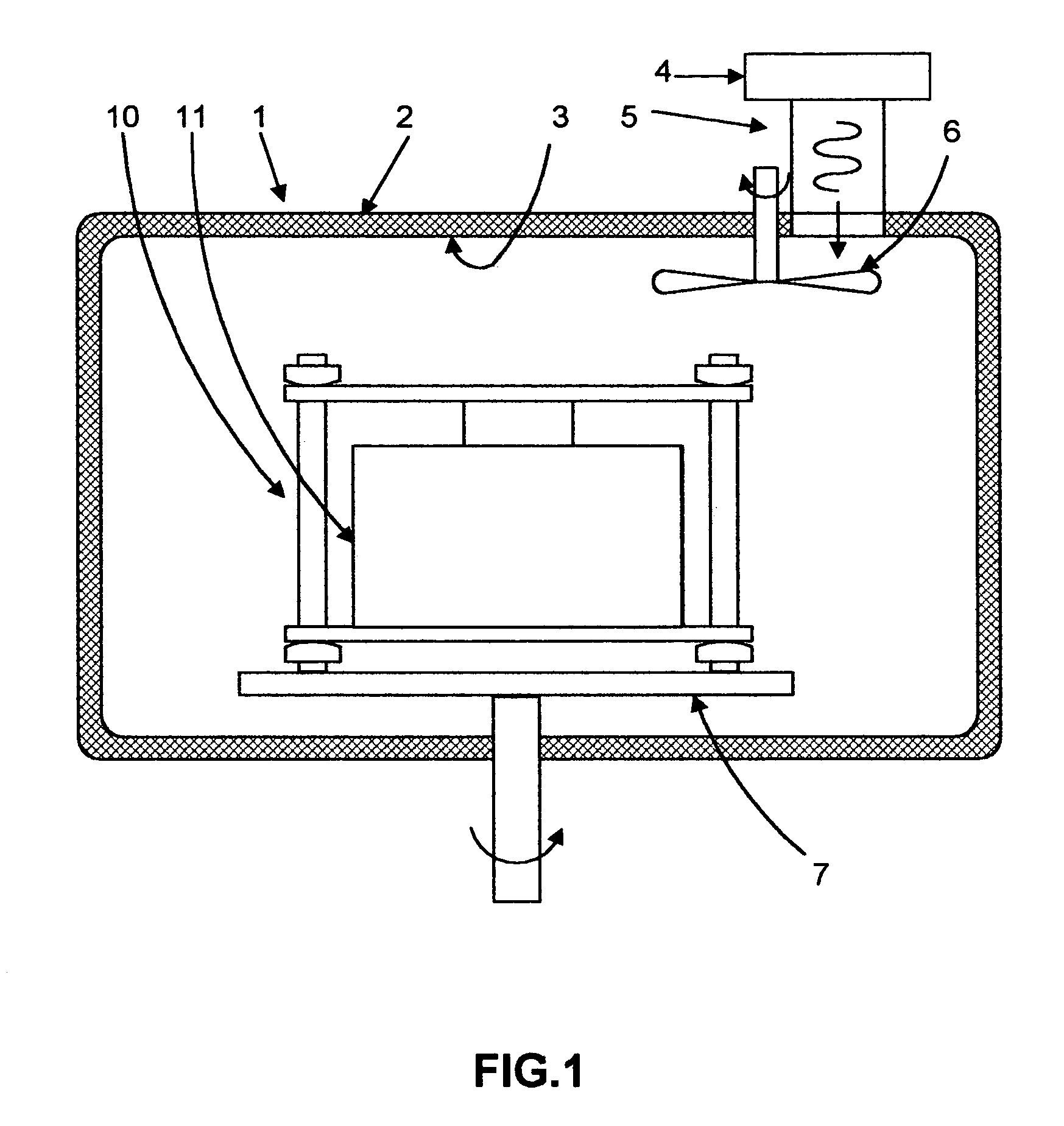
[0096]The molding process was performed in a batch microwave oven 1 operating at a frequency of 915 MHz. The dimensions of the chambe...


PUM

PropertyMeasurementUnit
temperaturesaaaaaaaaaa
pressuresaaaaaaaaaa
temperaturesaaaaaaaaaa

Abstract

A mold for relatively uniform heating and molding of a work material to form a workpiece using a microwave oven, includes upper and lower mold members and a sidewall mold member. The mold members are formed from materials selected to have an approximately equal effective thermosensitivity. The effective thermosensitivity of work material is its dissipation factor divided by the product of its dielectric constant, density and specific heat. The effective thermosensitivity of the material of mold layer of each mold member is its dissipation factor divided by the product of its dielectric constant, density, and specific heat and multiplied by the fraction of the mass of its mold layer divided by the total mass of this mold member. A metal sleeve is formed on an inner surface of the sidewall mold member with microwave absorbing material formed on the outside thereof and inner surfaces of the end mold members may also be coated with metal or other highly thermally conductive and wear resistant material.

Description

CROSS-REFERENCE TO RELATED APPLICATIONS[0001]This U.S. patent application is a continuation in part of and claims the benefit under 35 U.S.C. 120 of the filing date of U.S. patent application Ser. No. 10 / 157,324 filed May 29, 2002, now U.S. Pat. No. 6,984,352, and U.S. patent application Ser. No. 10 / 435,315 filed May 9, 2003.BACKGROUND OF THE INVENTION[0002]This invention relates generally to compression molding of polymers and composites by use of microwave energy, and more specifically to the design of molds for processing of such materials including the selection and / or modification of mold materials to form the mold to provide for uniform heating of polymers and composites by microwave energy. The molds and processes disclosed herein are adapted for molding parts of uniform thickness, variable thickness or complex shape. The developed technique may be used for molding of wide variety of polymers and composites from zero loss factor to conductive grades not withstanding the diele...

Claims


Application Information

Patent Timeline
Patent Type & Authority Patents(United States)
IPC IPC(8): B29C35/08B29C33/38B29C45/17B29C45/53B29C45/74
CPCB29C33/3828B29C33/3835B29C35/0805B29C45/53B29C45/74B29C45/1761B29C2035/0855
Inventor AKOPYAN, RAZMIK
Owner AKOPYAN RAZMIK
Why Eureka
Try Eureka