

Ink jet recording element with core shell particles
- Summary
- Abstract
- Description
- Claims
- Application Information
AI Technical Summary
Benefits of technology
Problems solved by technology
Method used
Image

Examples
example 1
Dye Stability Evaluation Tests
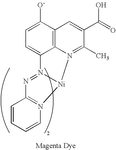
[0037]The dye used for testing was a magenta colored ink jet dye having the structure shown below. To assess dye stability on a given substrate, a measured amount of the ink jet dye and solid particulates or aqueous colloidal dispersions of solid particulates (typically about 10%–20.0% by weight solids) were added to a known amount of water such that the concentration of the dye was about 10−5 M. The solid dispersions containing dyes were carefully stirred and then spin coated onto a glass substrate at a speed of 1000–2000 rev / min. The spin coatings obtained were left in ambient atmosphere with fluorescent room lighting (about 0.5 Klux) kept on at all times during the measurement. The fade time was estimated by noting the time required for complete disappearance of magenta color as observed by the naked eye. Another way of determining face would be by noting the time required for the optical absorption to decay to less than 0.03 of the original value.
[0...
example 2
Preparation Base Coat Coating Solution:
[0046]A coating solution was prepared by mixing[0047](1) 242.6 g of water[0048](2) 225.6 g of Albagloss-s® precipitated calcium carbonate (Specialty Minerals Inc.) at 70 wt. %.[0049](3) 8.75 g of silica gel Crossfield 23F® (Crossfield Ltd.)[0050](4) 8.75 g of Airvol 125® poly(vinyl alcohol) (Air Products) at 10 wt. %[0051](5) 14.3 g of styrene-butadiene latex CP692NA® (Dow Chemicals Ltd.) at 50 wt. %.
Image Receiving Layer Coating Solution 1:
[0052]Image receiving coating solution 1 was prepared by combining 127.5 g deionized water, 34.5 g of high purity alumina (Catapal® 200, Sasol), 10.2 g of a 10% solution of polyvinyl alcohol (Gohsenol GH-17, Nippon Gohsei) 3.8 g of a core / shell particle emulsion (silica core and poly(butyl acrylate) shell, 40% solids) as prepared by the procedure as described in the Example 1 of U.S. Pat. No. 6,440,537, 13.6 g of poly(vinylbenzyl trimethylammonium chloride-co-divinylbenzene) (87:13 molar ratio) emulsion (15%...
example 3
Materials
[0067]An aqueous dispersion of colloidal silica, SiO2, having the trade name Nalco 23299®, (Ondeo Nalco Corporation, 40% solids) was used as the core. An aluminosilicate polymer prepared as a 16.66% sol in deionized water was used as the shell.
Preparation of Coating Solutions
Image Receiving Layer Coating Solution 6
[0068]Image receiving coating solution 6 was prepared by combining 10.5 g de-ionized water, 7.5 g of colloidal silica sol Nalco 2329®, 4 g of a 9% solution of polyvinyl alcohol (Gohsenol GH-23®, Nippon Gohsei). The mixture is allowed to mill on a roller mixer for 12 hours in presence of 5, 10 mm glass beads.
Image Receiving Layer Coating Solution 7
[0069]Image receiving coating solution 7 was prepared as in image receiving coating solution 6 except 0.9 g of aluminosilicate polymer sol was used to replace 0.375 g of the colloidal silica sol. The ratio of aluminosilicate polymer to silica was therefore 5 / 95. The de-ionized water level was adjusted to bring the total s...
PUM
| Property | Measurement | Unit |
|---|---|---|
| Percent by mass | aaaaa | aaaaa |
| Percent by mass | aaaaa | aaaaa |
| Particle size | aaaaa | aaaaa |
Abstract
Description
Claims
Application Information