
Method and apparatus for improving the performance of delta-sigma modulators

a technology of delta-sigma modulator and delta-sigma, applied in the field of comparator, can solve the problems of limiting the signal-to-noise ratio (snr) of the dsm, limiting the signal-to-noise snr performance that can be achieved, and deviations from ideal behavior. achieve the effect of improving the performance of the dsm and reducing the metastability errors

Active Publication Date: 2007-05-29
HRL LAB
View PDF5 Cites 1 Cited by
  • Summary
  • Abstract
  • Description
  • Claims
  • Application Information

AI Technical Summary

Benefits of technology

[0023]In accordance with the present invention the performance of a DSM is improved by an invention reducing the metastability errors produced by a comparator, wherein a second latch in the comparator is enabled with a delayed clock signal that has a lag TL relative to a clock signal that enables a first latch in the comparator to produce a first latch signal, such that TL≠nTc / 2 and TL≠0. The second latch is connected to the first latch and adapted to be enabled by the delayed clock signal to produce a second latch signal in response to a latch input signal produced in response to said first latch signal.

Problems solved by technology

However, even though recent advances in very-large-scale circuit integration (VLSI) have provided low-cost, low-power implementations of the digital signal postprocessing associated with these DSMs, the comparator delay times and power parameters required for providing an adequate signal-to-noise ratio (SNR) for the DSMs has limited their usefulness.
However the performance limitations of conventional comparator circuits result in deviations from this ideal behavior.
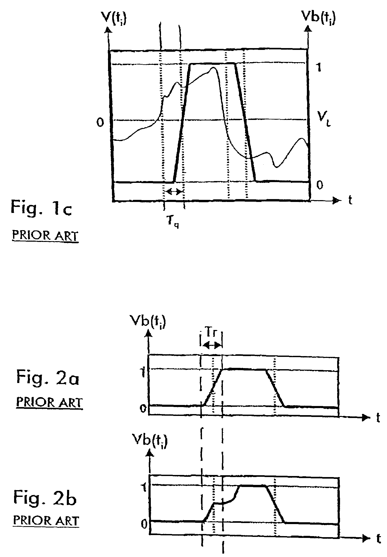
In particular, quantization latency Tq and the probability of a metastable state causing a comparator error Pmeta interact to limit the signal-to-noise SNR performance that can be achieved in DSM circuit designs having given frequency response and power efficiency parameters.
However, given that fc=1 / Tc, at higher signal frequencies where Tq>Tc / 2 that conventional compensation method is ineffective.
Metastability is a critically important factor in the design of synchronizer circuits, where it compromises the reliability of the output signals' synchronization.
However, this reduces the suitability of these synchronizers for use in high-frequency applications, applications that implementing frequencies above the conventional fmax values provided by these circuits.
Because all metastability errors are probabilistic rather than deterministic events, these errors cannot be effectively corrected or compensated, they must be prevented.
Unfortunately, the continuous-time DACs used in CT-DSMs increase the CT-DSMs' sensitivity to the metastability errors occurring during quantization.
However, the additional stages proposed by J. A. Cherry, et al. to reduce metastability in continuous-time modulators significantly increase the modulators' power consumption.
Thus, at least in theory, both the operating frequency and the power efficiency advantages of CT-DSMs are limited by the need to reduce the occurrence of metastability errors in CT-DSMs.
As the latency approaches one-half of the period of output signal's frequency Tc / 2, it becomes difficult to achieve stability in the feedback loop in these DSM devices.
The conventional trade-offs that increase quantization latency and the number of latch stages to reduce the incidence of these non-correctable probabilistic metastability errors in CT-DSMs reduce their operating frequency, and elevate the power consumption rate, respectively.

Method used


Image

  • Method and apparatus for improving the performance of delta-sigma modulators
  • Method and apparatus for improving the performance of delta-sigma modulators
  • Method and apparatus for improving the performance of delta-sigma modulators

Examples


Embodiment Construction

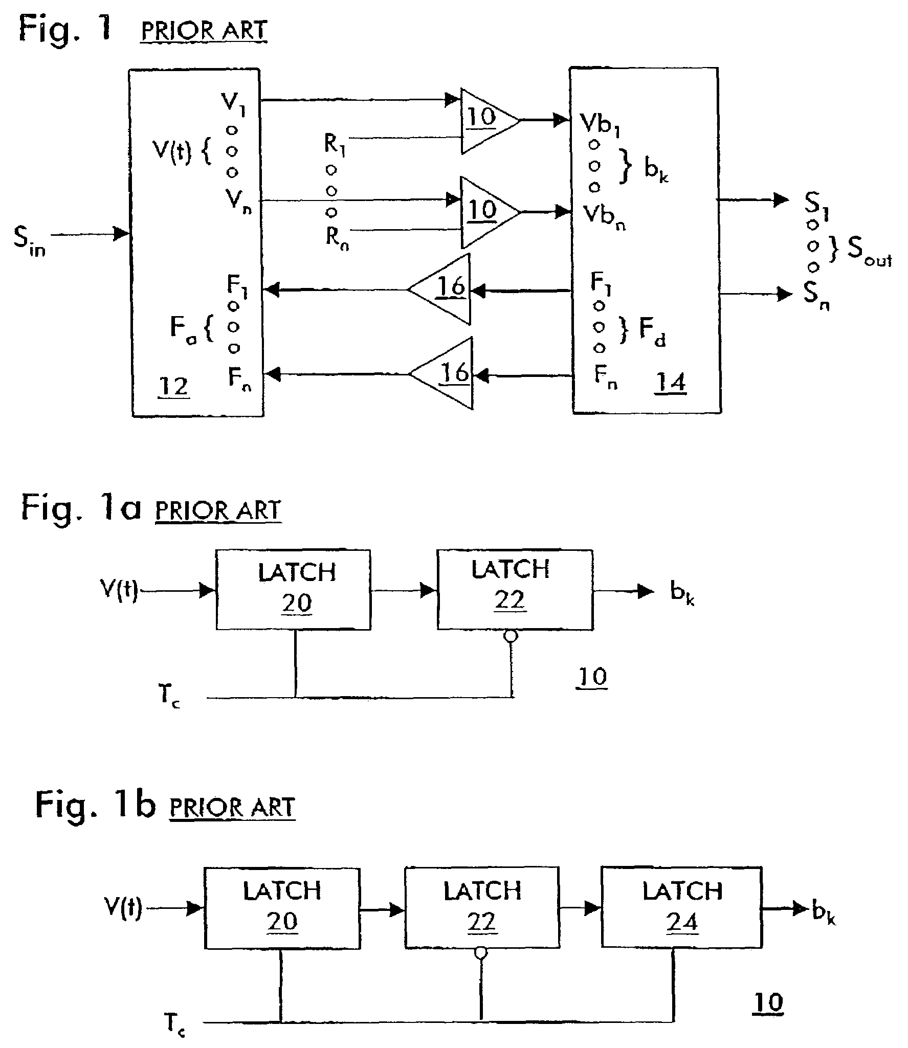
[0046]Each of the comparators 10 used in delta-sigma modulators (DSMs) is made up of at least three latch stages as shown in FIGS. 5b and 5c. Each latch stage is preferably a D-type transparent latch the same or similar to the bipolar latch circuit shown in FIG. 5a. The input to the first latch stage 20 in each comparator 10 is effectively analog, in contrast to the digital outputs provided to each subsequent latch stage in the comparator 10. Also, the first stage 20 of each comparator 10 in the DSM has a respective distinctive trip point, so that each comparator produces a respective distinctive stream of bits (bk) as its output (Vb).

[0047]The first latch stage 20 in each comparator circuit 10 samples the input signal at the falling edge of the clock signal and regenerates the input signal to a valid logic level. The last stage 24 in each comparator 10 provides a current source that permits the comparator's output S1–Sn to slew between the given voltage levels that define logic lev...


PUM


Abstract

A delta-sigma modulator that provides improved SNR performance in applications such as low-power mobile wireless communications and high frequency radar applications is disclosed. Multiple comparators 10, each comprising a sequence of three latches 20, 22, 24, connect the modulator's input filter circuit 12 to the modulator's output interfaces 14, providing quantization of the integrated, filtered signal provided by the filter circuit 12. A clock signal having a cycle period Tc enables a first latch 20 connected to the signal input of each comparator 10 to provide a digital signal to the signal input of a second latch 22. The second latch 22 supplies a digital signal to a third latch 24 in the sequence, in response to the signal received from the first latch 20, by a lagged clock signal derived from the given clock signal Tc by providing a first lag time TL where Tc / 2≧TL>0. A third latch in the sequence is enabled by a clock signal having a second lag time TS=Tc / 2+TE, and the delay TE<<Tc / 2. When TL=Tc / 2 the inverted clock signal supplied to the second latch is delayed and supplied to the third latch. When TL=TE the delayed clock signal supplied to the second latch is inverted and supplied to the third latch.

Description

CROSS REFERENCE TO RELATED APPLICATIONS[0001]This application claims the benefit of U.S. Provisional Patent Application Ser. No. 60 / 364,387 filed Mar. 13, 2002, the disclosure of which is hereby incorporated herein by reference.STATEMENT OF GOVERNMENT INTEREST[0002]This invention was related to work performed under the government contract entitled “CDRL A005 Low Power ADC Development Program”. The government has certain rights in this invention.BACKGROUND OF THE INVENTION[0003]1. Field of the Invention[0004]The present invention is related to analog to digital converter devices. More particularly, the present invention pertains to comparator devices used for digital signal generation.[0005]2. Discussion of Related Art[0006]The increasing importance of high-capacity wireless data communications has generated a demand for accurate, fast, and low-power-dissipation analog-to-digital converters to change high frequency analog inputs to digital signal formats. Delta-sigma modulators (DSMs...

Claims


Application Information

Patent Timeline
Patent Type & Authority Patents(United States)
IPC IPC(8): H04L7/00H03H11/26H04B14/06H03M3/00
CPCH03M3/374H03M3/424H03M3/454
Inventor CAPOFREDDI, PETER D.
Owner HRL LAB
Learn More