Dielectric recording apparatus, dielectric reproducing apparatus, and dielectric recording / reproducing apparatus

a recording apparatus and dielectric technology, applied in the field of dielectric recording apparatus, dielectric reproducing apparatus, dielectric recording/reproducing apparatus, can solve the problems of difficult to overcome the limit, the pickup is relatively large, and the recording density is limited to 1 t bit/inch/sup>, so as to achieve small and inexpensive

Inactive Publication Date: 2007-06-05
CHO YASUO +1
View PDF51 Cites 20 Cited by
  • Summary
  • Abstract
  • Description
  • Claims
  • Application Information

AI Technical Summary

Benefits of technology

[0009]It is therefore an object of the present invention to provide a dielectric recording apparatus, a dielectric reproducing apparatus, and a dielectric recording/reproducing apparatu

Problems solved by technology

However, the pickup is relatively large, which is not appropriate for high-speed reading, and the size of the recording pit is defined by the diffraction limit of light, so that its recording density is limited to 50 G bit/inch2.
However, the recording density is limited to 1 T bit/inch2 because of thermal fluctuation of magnetic recording information and the presence of a Bloch wall in a portion in which a code

Method used


Image

  • Dielectric recording apparatus, dielectric reproducing apparatus, and dielectric recording / reproducing apparatus
  • Dielectric recording apparatus, dielectric reproducing apparatus, and dielectric recording / reproducing apparatus
  • Dielectric recording apparatus, dielectric reproducing apparatus, and dielectric recording / reproducing apparatus

Examples


first embodiment

(First Embodiment of Dielectric Recording / Reproducing Apparatus)

[0081]A first embodiment of the dielectric recording / reproducing apparatus associated with the present invention will be explained with reference to FIG. 7.

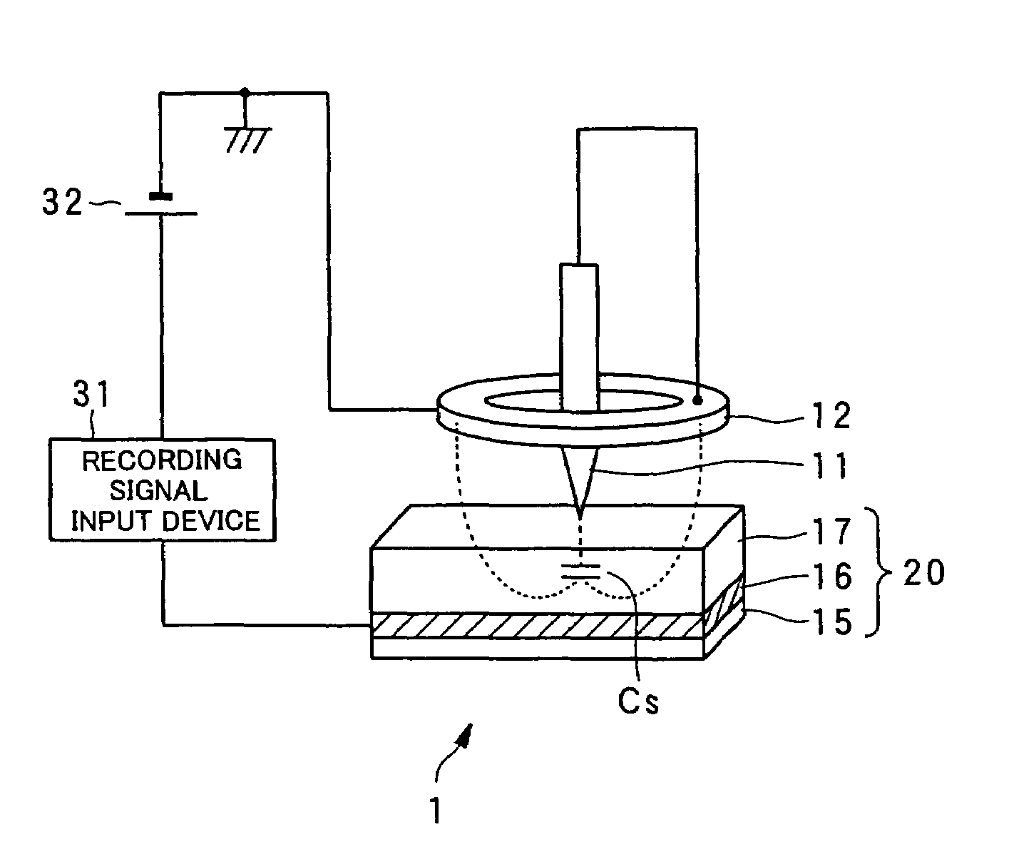
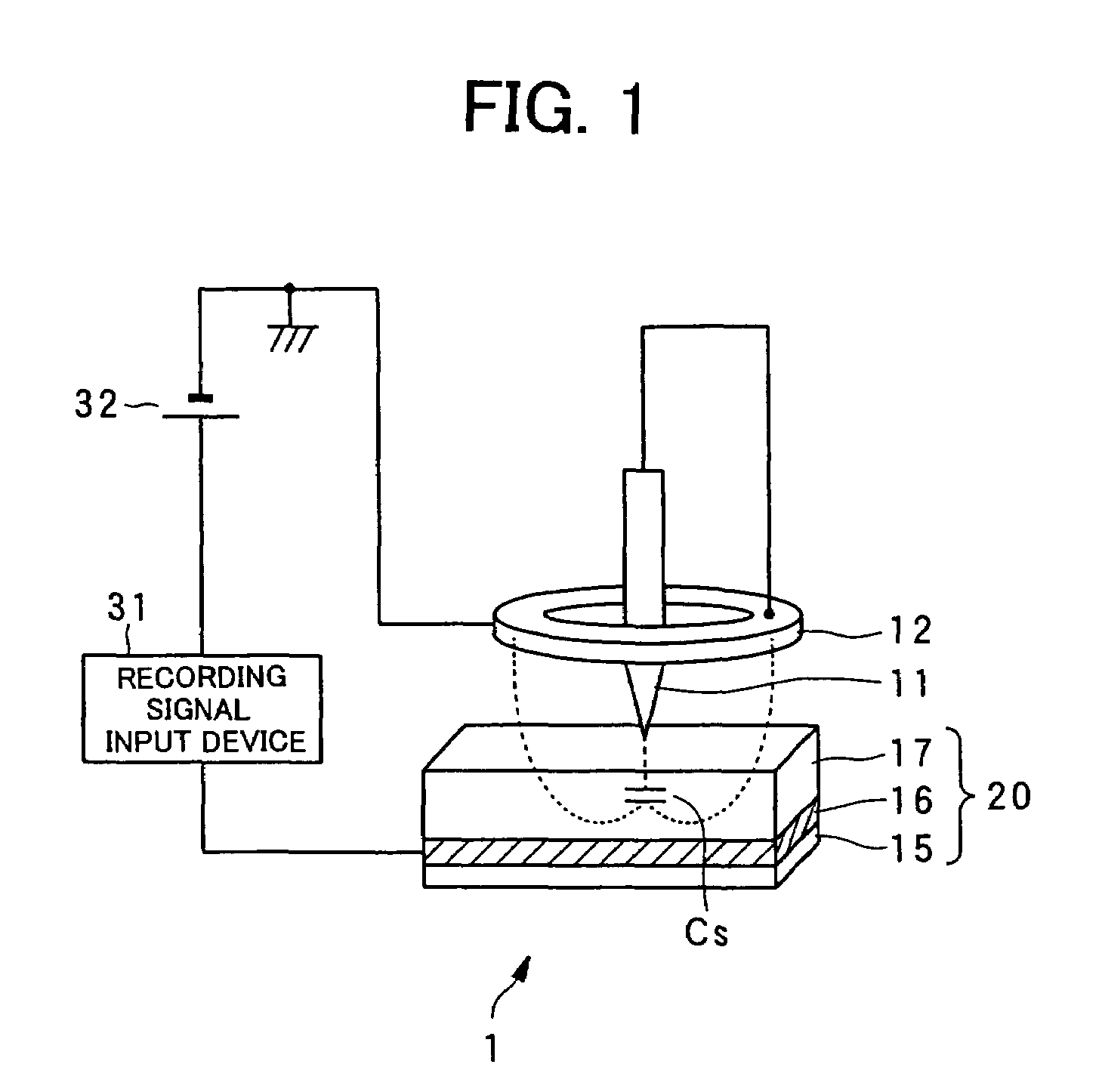
[0082]A dielectric recording / reproducing apparatus 3 is provided with: the probe 11 for applying an electric field with its tip portion facing to the ferroelectric material 17 of the ferroelectric recording medium 20; the return electrode 12 for returning the electric field applied from the probe 11; the inductor L placed between the probe 11 and the return electrode 12; the oscillator 13 which oscillates at a resonance frequency determined according to the inductor L and the capacitance Cs in a portion formed in the ferroelectric material 17 just under the probe 11 and polarized correspondingly to recorded data; a switch 30 for switching circuit connections depending on whether the data recording is performed or the data reproduction is performed; the recording sign...

second embodiment

(Second Embodiment of Dielectric Recording / Reproducing Apparatus)

[0086]A second embodiment of the dielectric recording / reproducing apparatus associated with the present invention will be explained with reference to FIG. 8.

[0087]A dielectric recording / reproducing apparatus 4 is provided with: the probe 11 for applying an electric field with its tip portion facing to the ferroelectric material 17 of the ferroelectric recording medium 20; the return electrode 12 for returning the high frequency electric field for signal reproduction applied from the probe 11; the inductor L placed between the probe 11 and the return electrode 12; the oscillator 13 which oscillates at a resonance frequency determined according to the inductor L and the capacitance Cs in a portion formed in the ferroelectric material 17 just under the probe 11 and polarized correspondingly to recorded information; the switch 30 for switching circuit connections depending on whether the data recording is performed or the ...

third embodiment

(Third Embodiment of Dielectric Recording / Reproducing Apparatus)

[0091]A third embodiment of the dielectric recording / reproducing apparatus associated with the present invention will be explained with reference to FIG. 9. The third embodiment indicates an example in the case where the inductance of the inductor L has a large effect on the frequency component of a recording signal.

[0092]A dielectric recording / reproducing apparatus 5 is provided with: the probe 11 for applying an electric field with its tip portion facing to the ferroelectric material 17 of the ferroelectric recording medium 20; the return electrode 12 for returning the high frequency electric field for signal reproduction applied from the probe 11; the inductor L placed between the probe 11 and the return electrode 12; the oscillator 13 which oscillates at a resonance frequency determined according to the inductor L and the capacitance Cs in a portion formed in the ferroelectric material 17 just under the probe 11 and...


PUM


Abstract

A dielectric recording/reproducing apparatus is provided with: a probe for applying an electric field to a dielectric material; a return electrode for returning the high frequency electric field for data reproduction; an inductor placed between the probe and the return electrode; an oscillator which oscillates at a resonance frequency determined according to the inductor and a capacitance formed in the dielectric material just under the probe; a switch for switching circuit connections depending on whether data recording is performed and data reproducing is performed; a recording signal input device for converting data to be recorded to generate a recording signal; a direct current voltage generation device for generating a direct current bias voltage to be applied to the dielectric material; a frequency-amplitude demodulator for demodulating an oscillation signal of the oscillator having the frequency that is changed depending on the capacitance owned by the dielectric material just under the probe; and a signal detector for detecting data from the demodulated signal.

Description

BACKGROUND OF THE INVENTION[0001]1. Field of the Invention[0002]The present invention relates to a dielectric recording apparatus, a dielectric reproducing apparatus, and a dielectric recording / reproducing apparatus for recording / reproducing information with high density in / from microdomains in a dielectric substance.[0003]2. Description of the Related Art[0004]As high-density, large-capacity recording / reproducing apparatuses of randomly accessible type, there are known an optical disc apparatus and a hard disc drive (HDD) apparatus. Moreover, a recording / reproducing technique using a scanning nonlinear dielectric microscopy (SNDM) for the nanoscale analysis of a dielectric (ferroelectric) material has been recently proposed by the inventors of the present invention.[0005]In optical recording, which uses an optical pickup with a laser as a light source, data is recorded by forming pits that are concave-convex on a disc surface or forming a crystal phase or amorphous phase of a phase...

Claims


Application Information

Patent Timeline
IPC IPC(8): G11B9/00G01Q60/00G01Q60/46G01Q80/00G01Q90/00G11B9/02G11B9/06G11B9/14G11B11/08
CPCB82Y10/00G11B9/02G11B9/06G11B9/14G11B9/1409G11B9/149G11B11/08
Inventor CHO, YASUOONOE, ATSUSHI
Owner CHO YASUO
Why Eureka
Try Eureka