Composite oxygen ion transport element

a technology of oxygen ion transport element and composite oxygen, which is applied in the direction of hydrogen/synthetic gas production, inorganic chemistry, chemical/physical processes, etc., can solve the problems of inhibiting flux performance, and achieve the effects of reducing expansion stress, high toughness, and increasing toughness

Active Publication Date: 2007-06-12
PRAXAIR TECH INC +1
View PDF5 Cites 47 Cited by
  • Summary
  • Abstract
  • Description
  • Claims
  • Application Information

AI Technical Summary

Benefits of technology

[0019]The pores can be of cylindrical configuration or of conical configuration. A porous layer can be located between the dense layer and the support layer to distribute permeated oxygen to the support layer and in case of the use of the composite oxygen ion transport element in a chemical reactor, to allow a hydrocarbon containing feed to reach the dense layer and thereby react with the oxygen. The presence of such a porous layer will act to further increase flux performance. In order to provide creep resistance at high temperatures and pressures, the support layer can be formed of an oxide dispersion strengthened metal, a metal-reinforced intermetallic alloy, a boron-doped Mo5Si3-based intermetallic alloy or combinations thereof. The support layer can of course also be formed of a ceramic. A ceramic that has the ability to withstand high temperatures and pressures higher than about 1000° C. and a pressure higher than about 300 psi is ceria toughened zirconia, yttria toughened zirconia and gadolinium doped ceria.
[0023]The fabrication of a support layer from the materials set forth above far exceed the performance of prior art materials with respect to creep and oxidation resistance at high temperatures and at high compositional stress. Moreover, it is believed that the use of the three phase mixture for the dense layer in connection with the above support layer materials has synergies that could not have been forecasted by the prior art use of such three phase mixtures. Without being held to any specific theory of operation, the inventors believe that the use of the ionic conductor and metal phases impart a high degree of toughness to the dense layer. “Toughness” here is meant to connote an increase in the area of a stress strain graph of the three phase material over that of the mixed conductor alone. Additionally, the use of the ionic conductor allows the dense layer to be fabricated with a very close thermal expansion coefficient match to the materials making up the support layer to reduce expansion stresses. As a result of the increased toughness, the dense layer will not easily fail as a result of remaining compositional stresses. Thus, the composite element is highly resistant to failure under the most severe of operating conditions. Prior art elements have not demonstrated such robustness.

Problems solved by technology

It would therefore, appear that a support formed in such a manner would inhibit flux performance.

Method used


Image

  • Composite oxygen ion transport element
  • Composite oxygen ion transport element
  • Composite oxygen ion transport element

Examples


example 1

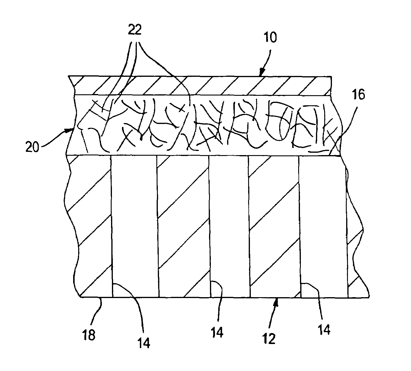
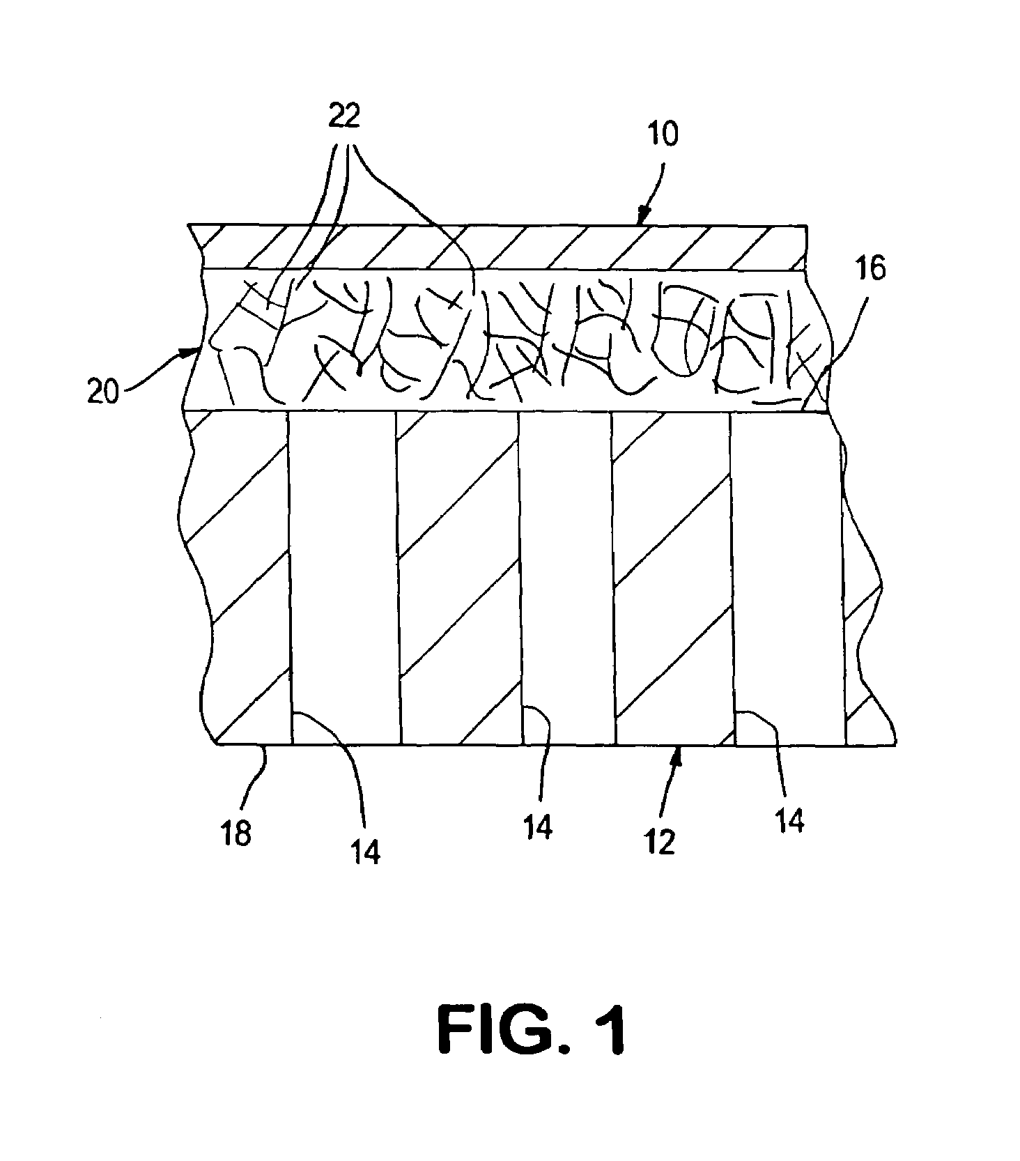
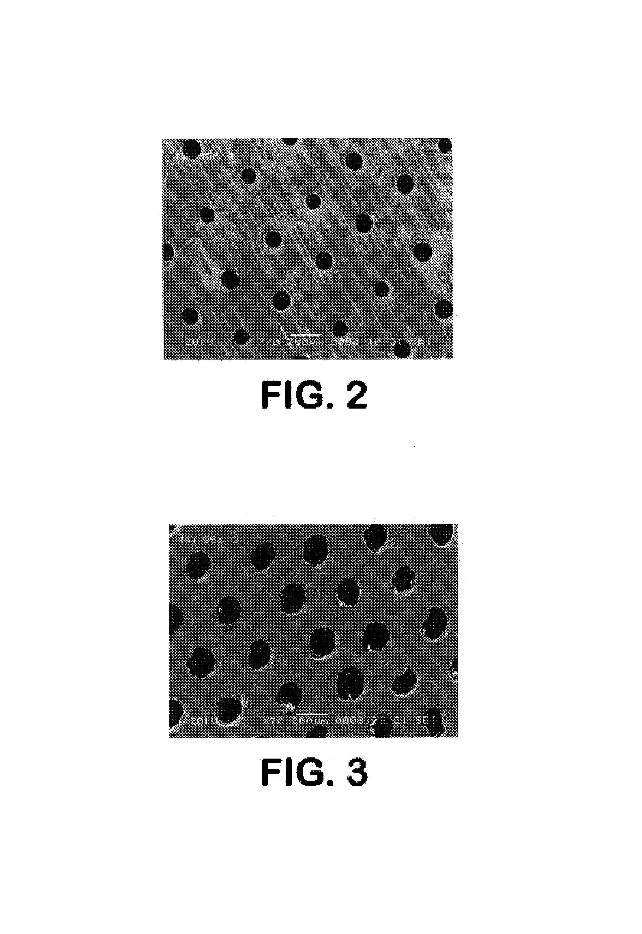
[0058]A metallic plate, about 1.5 mm in thickness, formed of MA956 alloy was obtained from Special Metals Corp. of Huntington, West Virginia, United States. Discs of about 30 mm in diameter were cut from the plate and perforated by E-beam drilling at Acceleron Inc. of East Granby, Connecticut, United States. The perforations were confined to a central area of the discs of about 16 mm. in diameter to form and thereby simulate support layer 12. The perforations were conical or as viewed in transverse, cross-section as being tapered. Thus, the openings on one side of the resultant support layer 12 had a diameter of about 75 microns as shown in FIG. 2 and the openings on the other side of the support layer 12, as seen in FIG. 3, has a diameter of about 150 microns.

[0059]The resultant perforated disc forming the support layer 12 was prepared for coating by using graphite as a pore filler. The disk was then plasma sprayed at the side with openings of about 150 microns with LSFC to produce...

example 2

[0064]In this example, a dense layer 10 was formed using mixed conductors, ionic conductors, and a metallic conductor. In this example, the components were chosen such that the dense layer had a resultant thermal expansion coefficient very close to that of support layer 12 which was fabricated from MA956 alloy.

[0065]The dense layer 10 on support layer 12 contained about 40% by weight LSFT, 40% by weight “CGO” (Ce0.8Gd0.2O), and about 20% by weight silver. The support layer 1 had a diameter of about 25.4 mm and thickness of about 1.5 mm. The difference between the coefficient of thermal expansion of the dense layer material and the MA956 support layer material is less than 1 ppm / ° K. over the range of about 100° C. to about 1000° C.

[0066]The material for the dense layer 10 was prepared by first obtaining about 40 grams of LSFT powder having particle sizes of between about 20 and about 30 microns agglomerated from primary particle sizes of between about 0.3 microns and about 0.5 micro...


PUM

PropertyMeasurementUnit
pore diameteraaaaaaaaaa
porosityaaaaaaaaaa

Abstract

A composite oxygen ion transport element that has a layered structure formed by a dense layer to transport oxygen ions and electrons and a porous support layer to provide mechanical support. The dense layer can be formed of a mixture of a mixed conductor, an ionic conductor, and a metal. The porous support layer can be fabricated from an oxide dispersion strengthened metal, a metal-reinforced intermetallic alloy, a boron-doped Mo5Si3-based intermetallic alloy or combinations thereof. The support layer can be provided with a network of non-interconnected pores and each of said pores communicates between opposite surfaces of said support layer. Such a support layer can be advantageously employed to reduce diffusion resistance in any type of element, including those using a different material makeup than that outlined above.

Description

CROSS REFERENCE TO RELATED APPLICATIONS[0001]This application is related to U.S. Provisional Patent Application Ser. No. 60 / 485,739 filed Jul. 10, 2003 which is hereby incorporated by reference as if fully set forth herein.U.S. GOVERNMENTAL INTEREST[0002]This invention was made with United States Government support under Cooperative Agreement number DE-FC26-01NT41096 awarded by the U.S. Department of Energy, National Energy Technology Laboratory. The United States Government has certain rights in this invention.FIELD OF THE INVENTION[0003]The present invention relates to a composite oxygen ion transport element having at least a dense layer capable of transporting oxygen ions and electrons and a support layer that incorporates a network of non-interconnected pores to reduce diffusion resistance. More particularly, the present invention relates to such a composite oxygen ion transport element in which the support layer is fabricated from a metal that is resistant to creep at high ope...

Claims


Application Information

Patent Timeline
Patent Type & Authority Patents(United States)
IPC IPC(8): C25B13/04B01D53/22B01D67/00B01D69/10B01D69/12B01D69/14B01D71/02C01B3/36C01B13/02C04B35/26C04B35/453C04B35/486C04B35/50C25B13/00
CPCB01D53/228B01D67/0046B01D67/0072B01D69/10B01D69/12B01D69/141B01D71/02B01D71/022B01D71/024C01B3/36C01B13/0255C04B35/01C04B35/2641C04B35/453C04B35/486C04B35/50B01D2257/104B01D2325/26C01B2203/061C01B2203/062C01B2210/0046C04B2235/3206C04B2235/3213C04B2235/3224C04B2235/3225C04B2235/3227C04B2235/3229C04B2235/3232C04B2235/3241C04B2235/3246C04B2235/3256C04B2235/3258C04B2235/3274C04B2235/3279C04B2235/3286C04B2235/3298C04B2235/404C04B2235/408C04B2235/5436C04B2235/80Y10T428/249956Y10T428/249954
Inventor CHEN, JACK C.BESECKER, CHARLES J.CHEN, HANCUNROBINSON, EARIL T.
Owner PRAXAIR TECH INC
Why Eureka
Try Eureka