Method and apparatus for reducing combustion engine emissions

a technology of combustion engine and combustion engine, which is applied in the direction of mechanical equipment, machines/engines, separation processes, etc., can solve the problems of soot/carbon emissions, most harmful to the environment, and the diesel engines of ships are great polluters of air, etc., and achieves the effect of reducing nitrogen emissions, simple structure and mounting

Inactive Publication Date: 2007-06-19
MARIOFF CORP OY
View PDF16 Cites 8 Cited by
  • Summary
  • Abstract
  • Description
  • Claims
  • Application Information

AI Technical Summary

Benefits of technology

[0023]Major advantages of the apparatus according to the invention are that it reduces nitrogen emissions effectively, in particular, when a diesel engine running at partial power is concerned, and in addition, its structure and mounting are simple. The apparatus can be adjusted very ac

Problems solved by technology

Exhaust gases from diesel engines contain various harmful combustion products, of which oxides of nitrogen, i.e. NOx, are the most harmful to the environment.
The diesel engines of ships are great polluters of air.
Soot/carbon emissions from the diesel engines, which are produced most when the engine runs at a low power level, also pose a problem.
Considerable nitrogen emissions are also produced when the engine runs at a low power level.
Typically, ship engines are run at a low power level when the ships are in ports, so the emissions are a considerable problem also when the ship is in port.
According to some studies, injecting water into the combustion chamber may increase smoke emissions.
Fuel consumption may also rise, if large amounts of water are injected into the engine.
The HAM method has a drawback that the load capacity of the diese

Method used


Image

  • Method and apparatus for reducing combustion engine emissions
  • Method and apparatus for reducing combustion engine emissions
  • Method and apparatus for reducing combustion engine emissions

Examples


Embodiment Construction

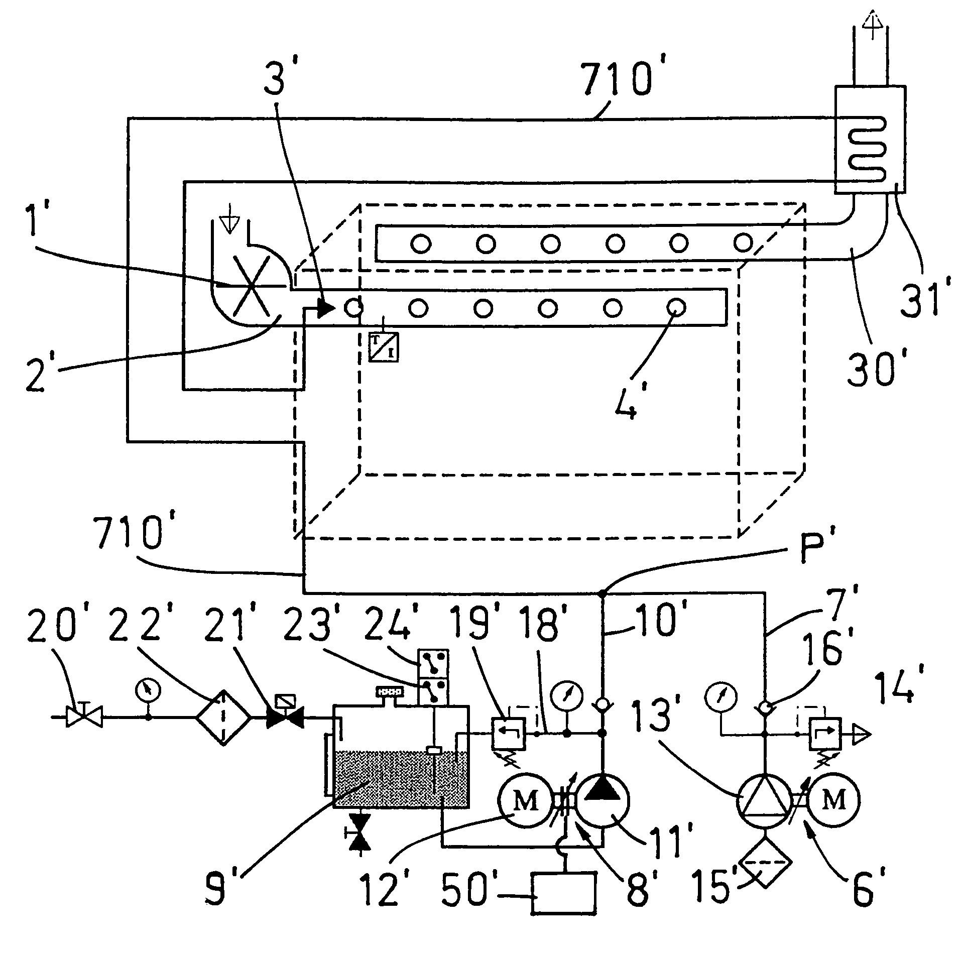
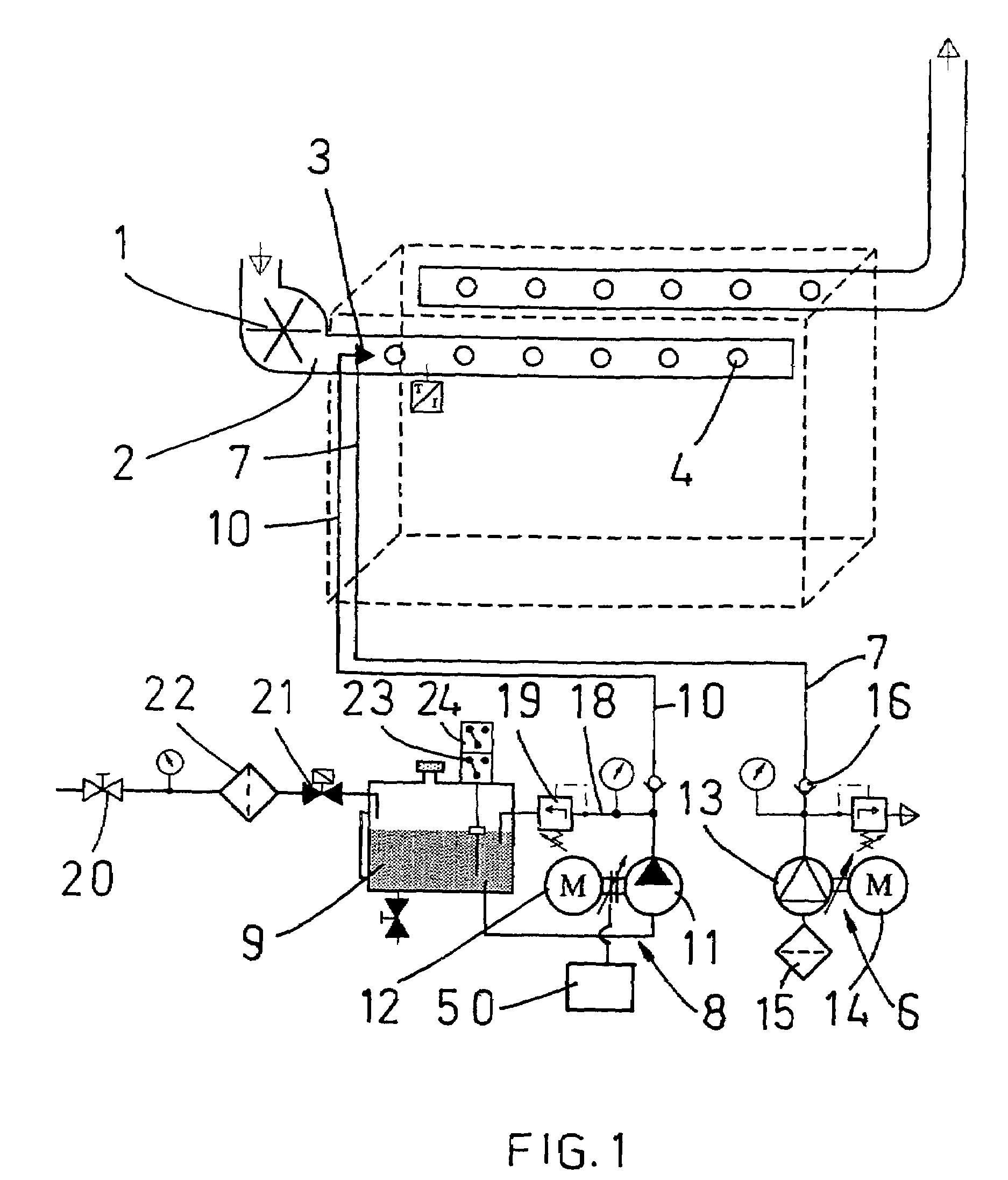
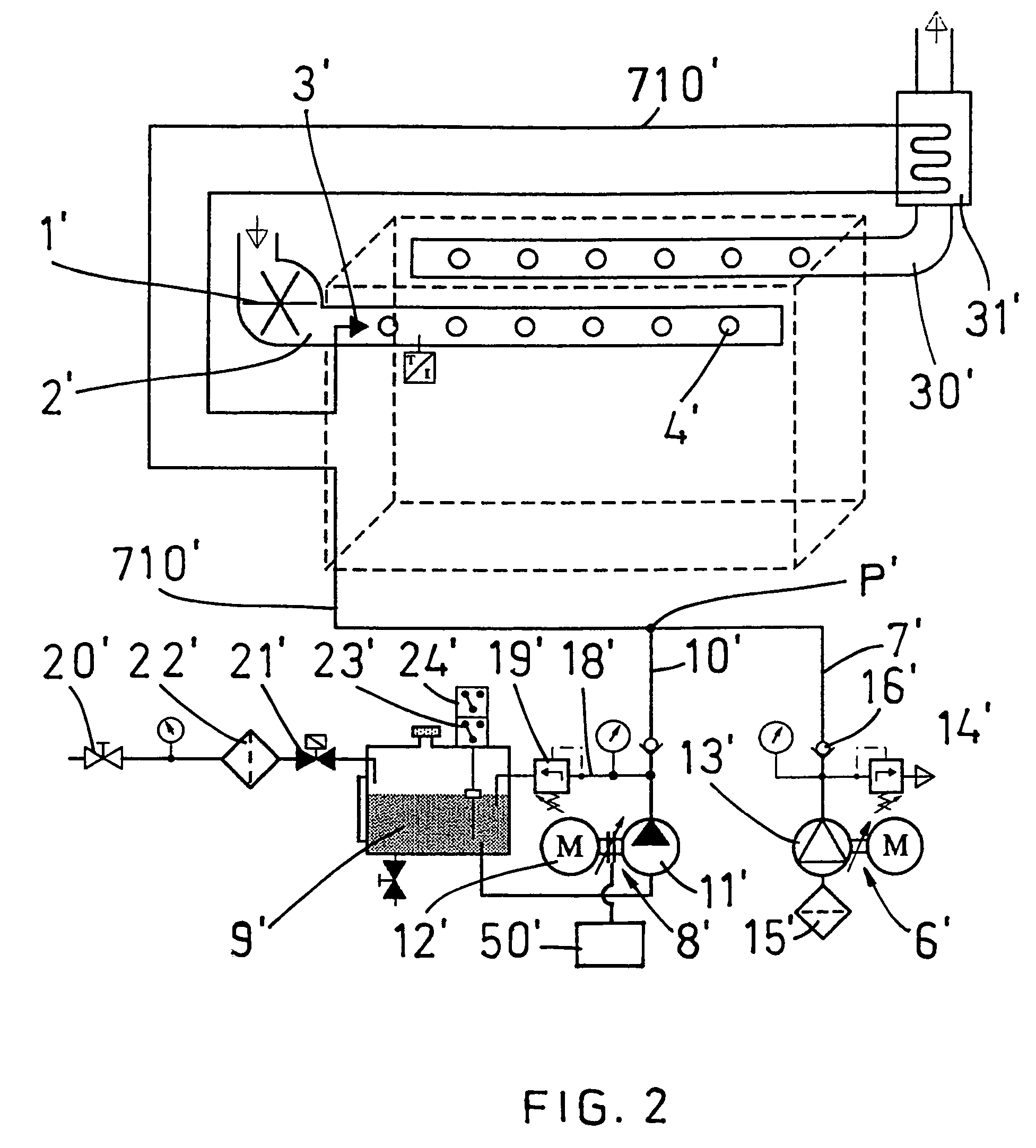
[0029]FIG. 1 shows a large 6-cylinder diesel engine of a ship. The engine is provided with a charger 1, which feeds pressurized combustion air into suction pipelines 2. In order to reduce nitrogen emissions from the engine the suction pipelines 2 are provided with a spray head 3, which is arranged to feed a mixture of gas and water mist into the suction manifold, wherefrom said mixture passes into the engine cylinders 4. Because the mixture of gas and aqueous mist enters the cylinders, the combustion temperature in the cylinders 4 decreases. The combustion temperature decreases efficiently both when the engine runs at full power and when it runs at partial power. The reason why the combustion temperature decreases efficiently also when the engine runs at partial power is that the spray head 3 also feeds gas into the suction pipelines. Gas feeding reduces the size of water drops, which is important, so that the water drops would vaporize easily and quickly also when the engine runs a...


PUM


Abstract

The invention relates to a method for cleaning exhaust gases from a combustion engine, in which method humid air is fed into the combustion chamber of the combustion engine. In order to reduce nitrogen emissions effectively, particularly when a diesel engine is running at partial power, and in order for the method to be very accurately adjustable to meet the requirements of each particular engine application and use, in accordance with the invention, a mixture of gas and aqueous mist is fed with a spray head (3) into a space (2), which leads to the combustion chamber. The method can be readily implemented by an apparatus, which can be mounted in a small space without having to make substantial changes in the combustion engine. The invention also relates to an apparatus for cleaning exhaust gases from a combustion engine.

Description

BACKGROUND OF THE INVENTION[0001]The invention relates to a method for cleaning exhaust gases from a combustion engine, in which method humid air is fed into a combustion chamber of the engine, whereby a mixture of gas and aqueous mist is fed with a spray head into a space that leads to the combustion chamber.[0002]The invention also relates to an apparatus for feeding humid air into a combustion engine, the apparatus comprising a spray head for feeding aqueous mist into a space in the combustion engine, gas feeding means for feeding gas into the spray head, liquid feeding means for feeding aqueous liquid into the spray head and mixing means for providing a mixture of gas and aqueous mist from the spray head into said space, which is arranged to be in flow connection with the combustion chamber of the combustion engine and to supply the mixture of gas and aqueous mist into the combustion chamber. This kind of apparatus is known in connection with gas turbine engines, and the purpose...

Claims


Application Information

Patent Timeline
IPC IPC(8): F02B47/04F02B47/02B01D53/92F01N3/04F01N3/08F02B3/06F02M25/028F02M25/032
CPCB01D53/92F01N3/04F02M25/028F02M25/0221F02M25/0225F02M25/0227F02B3/06Y02T10/121Y02T10/20Y02T10/12F02B47/04
Inventor SUNDHOLM, GORAN
Owner MARIOFF CORP OY
Why Eureka
Try Eureka