Method for providing high bandwidth force feedback with improved actuator feel
What is Al technical title?
Al technical title is built by PatSnap Al team. It summarizes the technical point description of the patent document.
a high-bandwidth force and actuator technology, applied in the field of interface devices, can solve the problems of affecting the real-time effect of forces, affecting the operation of the motor, so as to achieve the effect of increasing the realism of forces
Inactive Publication Date: 2007-06-26
IMMERSION CORPORATION
View PDF137 Cites 140 Cited by
Summary
Abstract
Description
Claims
Application Information
AI Technical Summary
This helps you quickly interpret patents by identifying the three key elements:
Problems solved by technology
Method used
Benefits of technology
[0011]The present invention is directed to implementations of a human/computer interface device for controlling and providing force feedback
Problems solved by technology
One problem presented by prior art force feedback and haptic systems is the “cogging” effect occurring with the use of these types of motors.
This effect is sometimes described as “detenting” or “ratcheting” and can result in substantial variation in the output torque of the motor, both when powered and unpowered.
Cogging can be particularly problematic in force feedback devices because the motor rotational speed is so slow that the user is often able to feel each individual torque disturbance as the user manipulatable object is moved and/or as forces are output on the user object.
This effect is often perceived by users as “roughness” or “pulsations” and is usually equated with poorly-performing force feedback or haptic systems.
If low friction, high stiffness transmission systems are used, the cogging effect also is quite noticeable to the user, unlike in high friction systems such as gear systems which produce enough noise themselves to mask the cogging effect.
Thus, the cogging effect reduces the realism and fidelity of forces in high bandwidth force feedback systems which are used to accura
Method used
Image
Click on the blue label to locate the original text in one second.
Reading with bidirectional positioning of images and text.
Examples
Embodiment Construction
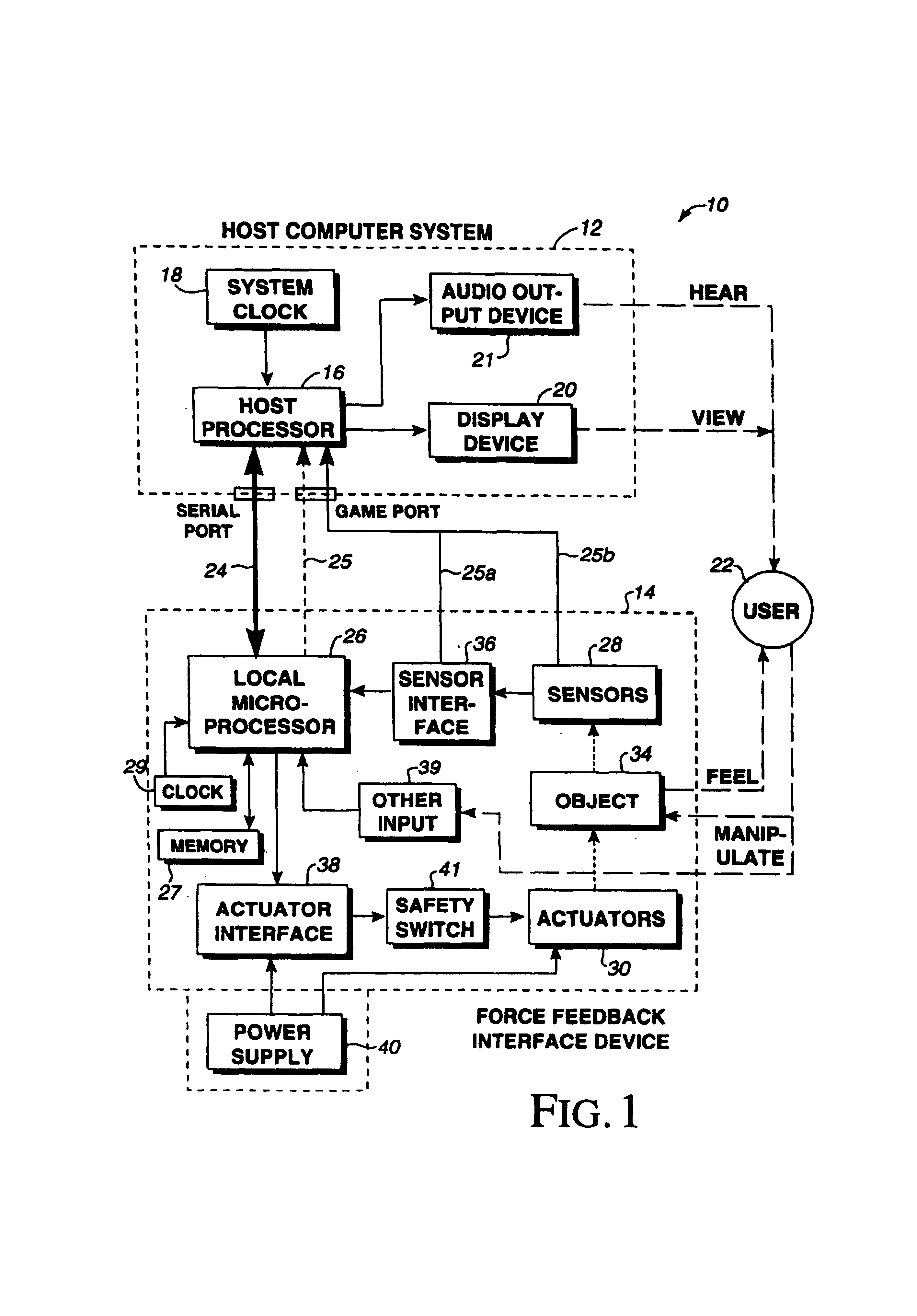
[0030]FIG. 1 is a block diagram illustrating a generic control system 10 of the present invention for a force feedback interface device controlled by a host computer system. Control system 10 includes a host computer system 12 and an interface device 14 (or “force feedback peripheral”).
[0031]Host computer system 12 (“host”) is preferably a personal computer, such as an IBM-compatible or Macintosh personal computer, or a workstation, such as a SUN or Silicon Graphics workstation. For example, the host computer system can a personal computer which operates under the MS-DOS or Windows operating systems in conformance with an IBM PC AT standard. Alternatively, host computer system 12 can be one of a variety of home video game systems commonly connected to a television set, such as systems available from Nintendo, Sega, or Sony. In other embodiments, home computer system 12 can be a more application specific “set top box” or “internet computer” which can be used, for example, to provide ...
PUM
Abstract
A method and apparatus for providing low-cost, realistic force feedback including an improved actuator. The invention provides force sensations to a user and includes an interface device coupled to a host computer and allowing a user to interact with a host application program. A user object, such as a joystick, is moveable by a user in at least one rotary degree of freedom. A sensor reports a locative signal to the host computer to indicate a position of the user object. An actuator outputs forces on the user object in response to signals from the host computer and program. The actuator includes a housing, a set of grounded magnets provided on opposing surfaces of the housing and creating a magnetic field, and a rotor coupled to the user object positioned between the magnets. The rotor rotates about an axis of rotation and includes a shaft and teeth spaced around the shaft. An electric current flows through one or more coils on the teeth to cause the rotor to rotate. The teeth and the magnets are provided in a skewed, helical arrangement relative to each other so that, as the rotor rotates, a first tooth gradually exits the magnetic field as the next consecutive tooth gradually enters the magnetic field, thereby significantly reducing a cogging effect of the rotor when the user object is moved by the user and increasing the fidelity of forces experienced by the user.
Description
CROSS REFERENCE TO RELATED APPLICATIONS[0001]This application is a continuation application of application Ser. No. 09 / 223,228, filed Dec. 30, 1998 now abandoned, which is a divisional application of application Ser. No. 08 / 791,020, filed Jan. 27, 1997 now U.S. Pat. No. 6,050,918, which is a continuation-in-part application of application Ser. No. 08 / 623,660, filed Mar. 28, 1996, now U.S. Pat. No. 5,691,898; the entire content of each which is hereby incorporated by reference. This application also is a continuation of and claims priority under 35 U.S.C. 120 to co-pending U.S. Pat. application Ser. No. 10 / 079,379 filed Feb. 19, 2002, which is a continuation application of application Ser. No. 09 / 258,749 filed Feb. 26, 1999, now U.S. Pat. No. 6,348,911, which is a continuation application of application Ser. No. 08 / 825,726 filed Apr. 2, 1997, now U.S. Pat. No. 5,929,607, which is a divisional application of application Ser. No. 08 / 623,660 filed Mar. 28, 1996, now U.S. Pat. No. 5,691,...
Claims
Application Information
Patent Timeline
Application Date:The date an application was filed.
Publication Date:The date a patent or application was officially published.
First Publication Date:The earliest publication date of a patent with the same application number.
Issue Date:Publication date of the patent grant document.
PCT Entry Date:The Entry date of PCT National Phase.
Estimated Expiry Date:The statutory expiry date of a patent right according to the Patent Law, and it is the longest term of protection that the patent right can achieve without the termination of the patent right due to other reasons(Term extension factor has been taken into account ).
Invalid Date:Actual expiry date is based on effective date or publication date of legal transaction data of invalid patent.