
Pulsed vapor desorber

Active Publication Date: 2007-07-17
LEIDOS SECURITY DETECTION & AUTOMATION INC
View PDF6 Cites 22 Cited by
  • Summary
  • Abstract
  • Description
  • Claims
  • Application Information

AI Technical Summary

Benefits of technology

[0012]According to the present invention, a method for the rapid desorption of adsorbed gases in a vapor concentrator system is described. This method includes providing a substrate with a surface for adsorbing target vapor, accumulating target vapor on the substrate surface, providing a short duration pulse of photons from a lamp onto the substrate surface to desorb the target vapor, and providing a carrier gas flow for transporting the desorbed target vapor to an analytical instrument for detecting the target vapor.
[0016]According further to the present invention, the pulse of photons may be in optical communication with the entirety of the surface for adsorbing target vapor without significant shadowing of portions of the surface. Full optical communication maximizes vapor desorption and allows vapor accumulated during a concentration cycle to be completely cleared before a subsequent cycle. The optical communication may optionally include an optically transparent window, an optically transparent lens, a mirror for concentration and containment of the pulse of photons, a light pipe, or an optical fiber. The optically transparent window may optionally be a component of the lamp.
[0018]In one embodiment, a high brightness pulsed lamp, such as a xenon-filled lamp, is used to illuminate the adsorbing surface for a time period less than 100 milliseconds, for example, less than 1 millisecond. Additionally, the geometry of the adsorbing surface may be totally illuminated without any significant shadowing. The energy transmitted by the pulse of photons from the lamp may be much smaller than that required to heat the entire substrate of the adsorbing surface to a given temperature. Still, the surface layer of the adsorbing surface, which only includes a few hundred monolayers of atoms, may not conduct this sudden influx of energy away instantaneously, and thus the adsorbing surface may momentarily become relatively warm. The effect may last only for a few milliseconds before thermal conduction dissipates the energy into the substrate of the adsorbing material, and the surface layers cool off.
[0019]The advantages of this method are as follows: 1) relatively little energy is needed to warm only the surface layer of the adsorber, which is useful in field portable implementations, 2) the adsorbing surface is purged and ready to be reused immediately, that is, no time is needed for cool down, and 3) all of the target vapors are released into the carrier gas stream relatively quickly (e.g., within about 1 millisecond), providing a much higher concentration of target vapor than can be obtained by thermally heating the entire adsorbing mass, which may require seconds to accomplish.
[0021]In one embodiment, the concentration method avoids the accumulation of particles, as compared to the desired vapors. Particles may be relatively massive, and the pulsed lamp may not produce sufficient photonic energy to completely vaporize them. Incompletely vaporized particles may continue to emit vapor during later cycles of adsorption / desorption, causing false positive indications in the analysis instrument. Particles can be excluded from the interior of the chamber by, for example, limiting flow rates to reduce turbulence, using a cyclone dust separator, or using a filter.

Problems solved by technology

The sensitivity of these well-known techniques is often limited by the low concentration of the target chemical vapors that are present at their input ports.
Molecules of interest may undesirably adsorb onto surfaces in the sampling flow path that are not part of the concentration device.
All of these concentration methods are limited by the fact that the relatively large mass of the substrate must change temperature, a relatively slow process.

Method used


Image

  • Pulsed vapor desorber
  • Pulsed vapor desorber
  • Pulsed vapor desorber

Examples


Embodiment Construction

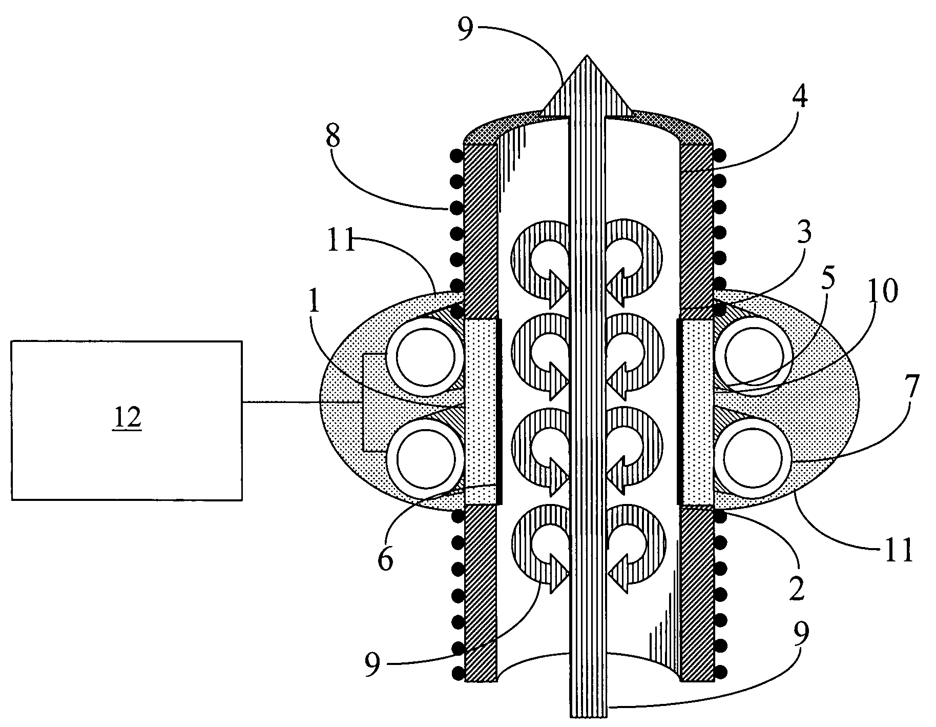
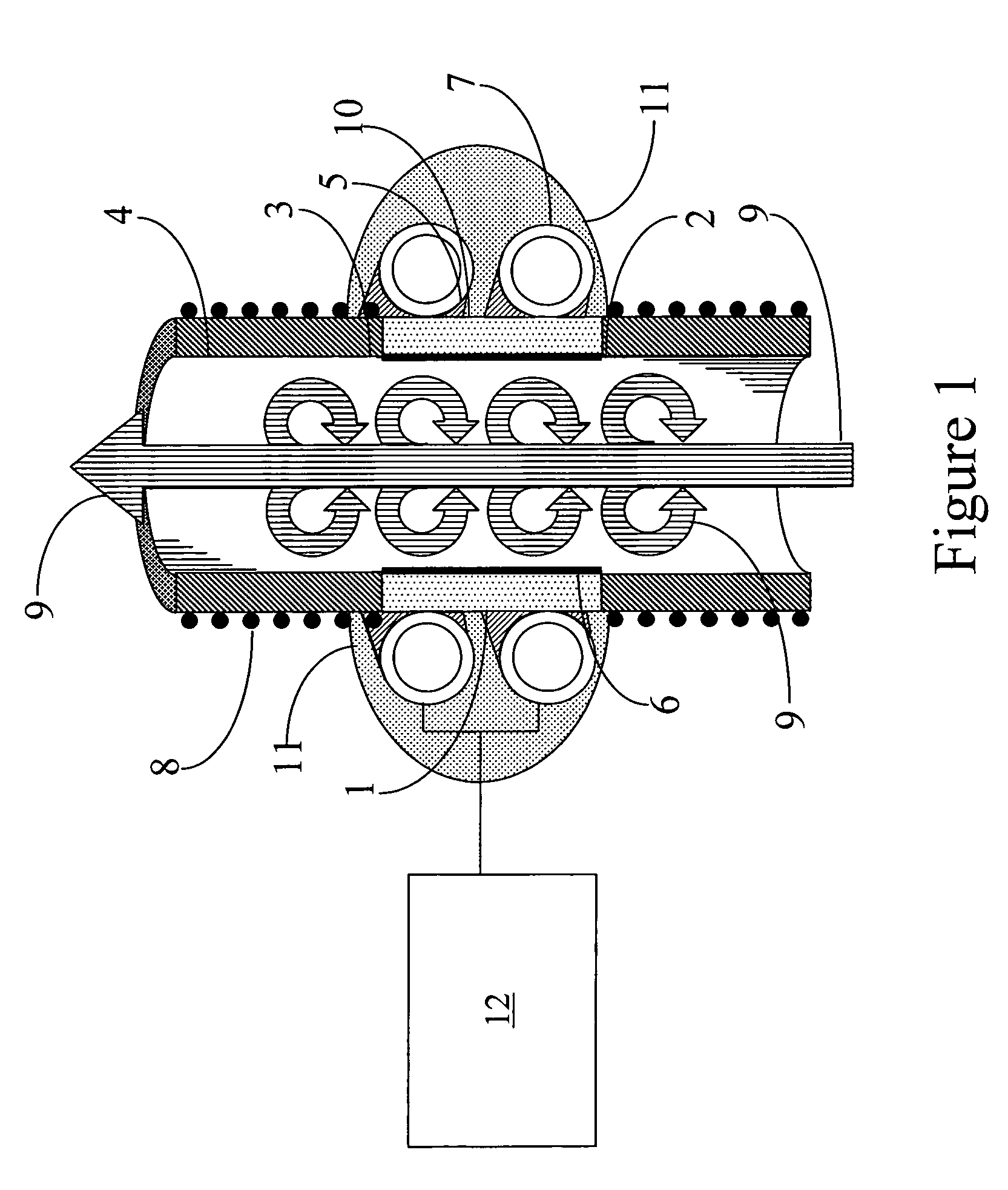
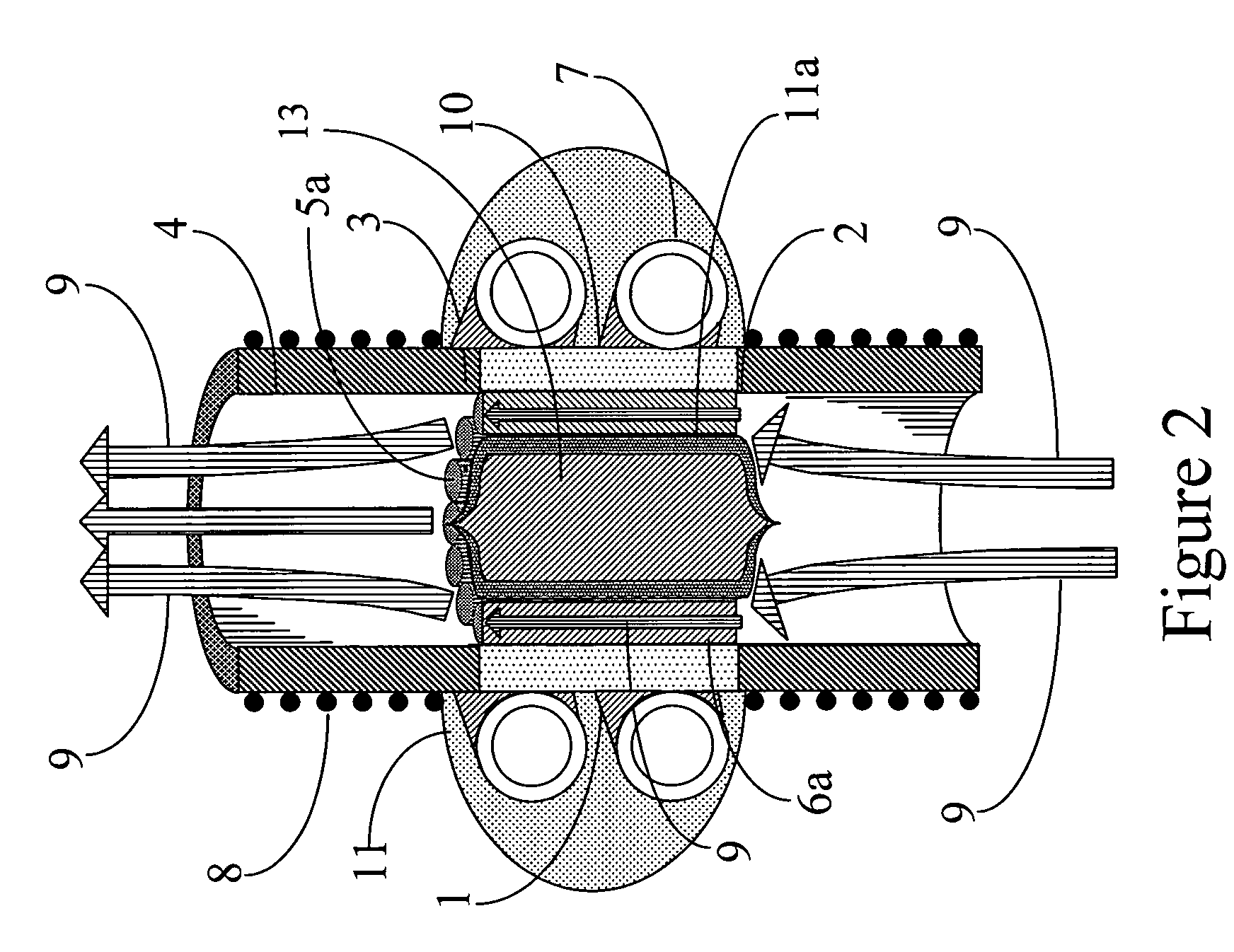
[0027]A possible embodiment of a pulsed desorption vapor concentrator is illustrated in FIG. 1. While various embodiments may differ in details, FIG. 1 shows many of the basic features of a type of concentrator that could be used in connection with the pulsed vapor desorption method described herein. The concentrator includes a chamber 1, which in this embodiment is also an optical communication window 10 connecting a pulsed lamp 7 to a substrate 5 of a concentrating surface 6. In this embodiment, the substrate 5 is also the same as the chamber 1 and the optical communication window 10. A mixture of carrier gas and trace target vapor 9 enters the chamber 1 through an entrance orifice 2. Due to turbulence, the flow interacts with the concentrating surface 6. The concentrating surface 6 may be the wall of the optical communication window 10 or it may optionally be a thin, semitransparent coating on the optical communication window 10. A heater 8 is used to warm any tubulation that may...


PUM


Abstract

Vapor concentrators are used to provide a higher concentration of trace target vapor than would normally be available in the environment. This is accomplished by allowing the trace target vapor to adsorb onto a concentrating surface and subsequently releasing the trace target vapor by heating the surface. An improved desorbing method is providing by a fast pulse of photons, which only heats the near surface region, rather than the entire mass of the substrate on which the concentrating surface resides. Since all of the trace target vapor is released in a short time interval, the vapor is less diluted by carrier gas than would occur during the slower temperature ramp that results when the entire substrate mass is heated. A more highly concentrated target vapor is produced with less input of energy.

Description

CROSS-REFERENCE TO RELATED APPLICATIONS[0001]This application claims priority to U.S. Provisional Application No. 60 / 473,649, filed May 28, 2003, which is incorporated herein by reference.BACKGROUND OF THE INVENTION[0002]1. Field of the Invention[0003]This invention relates to a vapor concentrator that may interface to an instrument that detects trace quantities of chemicals present as vapors in air or other gases, or liberated as vapors from condensed phases, such as particles or solutions, and more particularly relates to the desorption of concentrated samples of such vapors for injection into analytical instruments.[0004]2. Description of Related Art[0005]The quantitative analysis and identification of trace organic vapor species is rapidly becoming important in a variety of applications. For example, trace vapors are used to indicate the presence or recent handling of various explosive compounds. Detection of toxic chemicals, narcotic substances, fumes from food decay, fumes fro...

Claims


Application Information

Patent Timeline
IPC IPC(8): B01D53/02G01N1/04G01N1/22G01N1/24G01N1/40G01N30/12
CPCG01N1/2214G01N1/40G01N30/12G01N1/24G01N2001/045G01N2001/2223
Inventor BELYAKOV, VLADIMIR V.JONSEN, DANIEL E.BUNKER, STEPHEN N.
Owner LEIDOS SECURITY DETECTION & AUTOMATION INC
Learn More