One-dimensional arrays on optical fibers

a technology of optical fibers and arrays, applied in the field of one-dimensional arrays on optical fibers, can solve the problems of synthesis and analysis of an entire library, which may contain millions of compounds, and the cost and cost of reading a chip is beyond what can reasonably be used in a doctor's office, and the cost and complexity of reading a chip are increasing time-consuming and cost-intensiv

Inactive Publication Date: 2007-07-17
UMW RES FOUND INC
View PDF20 Cites 24 Cited by
  • Summary
  • Abstract
  • Description
  • Claims
  • Application Information

AI Technical Summary

Benefits of technology

[0010]In another aspect, the present invention provides a novel method of synthesizing an array of compounds on an optical fiber. The compounds are synthesized off of functional groups on the optical fiber or on the cladding of the optical fiber. The functional groups are subjected to a series of reactions conditions, wherein each set of reaction conditions cycles with a specific period along the support. Each reaction condition of the series is identifiable as a function of distance along the fiber. This parallel method of synthesis along a linear optical fiber support allows each newly synthesized compound to be identified by its position along the fiber.
[0011]In yet another aspect, the present invention provides a method of analyzing the agents along the array. The compounds in the array can be assayed based on any desired activity. The assay will change an optical property at the site of the compound based on whether the compound has the activity being assayed for. Preferably, the optical characteristic measured is fluorescence. The compounds along the fiber can be distinguished in the time domain by excitation with a very narrow laser pulse, and detection of the resulting fluorescence emission that has been captured by the fiber. An enormous advantage of such a linear array along an optical fiber is that alignment of only one end of the fiber is needed to couple excitation and emission to every sensor element. The present invention also provides a system for analyzing the agents along the linear array. The system comprises a light source, a linear array of agents on a optical fiber, and a detector.

Problems solved by technology

However, as these chips become larger and larger, the readout of the chip becomes increasingly time-consuming and cost intensive, and more sophisticated instrumentation is required to analyze the array.
Even today, the expense and complexity of reading a chip is beyond what can reasonably be used in a doctor's office.
However, the synthesis and analysis of an entire library, which may contain millions of compounds, is very time consuming and costly, and full scale library analysis is rarely done.

Method used


Image

  • One-dimensional arrays on optical fibers
  • One-dimensional arrays on optical fibers
  • One-dimensional arrays on optical fibers

Examples


example 1

Scheme

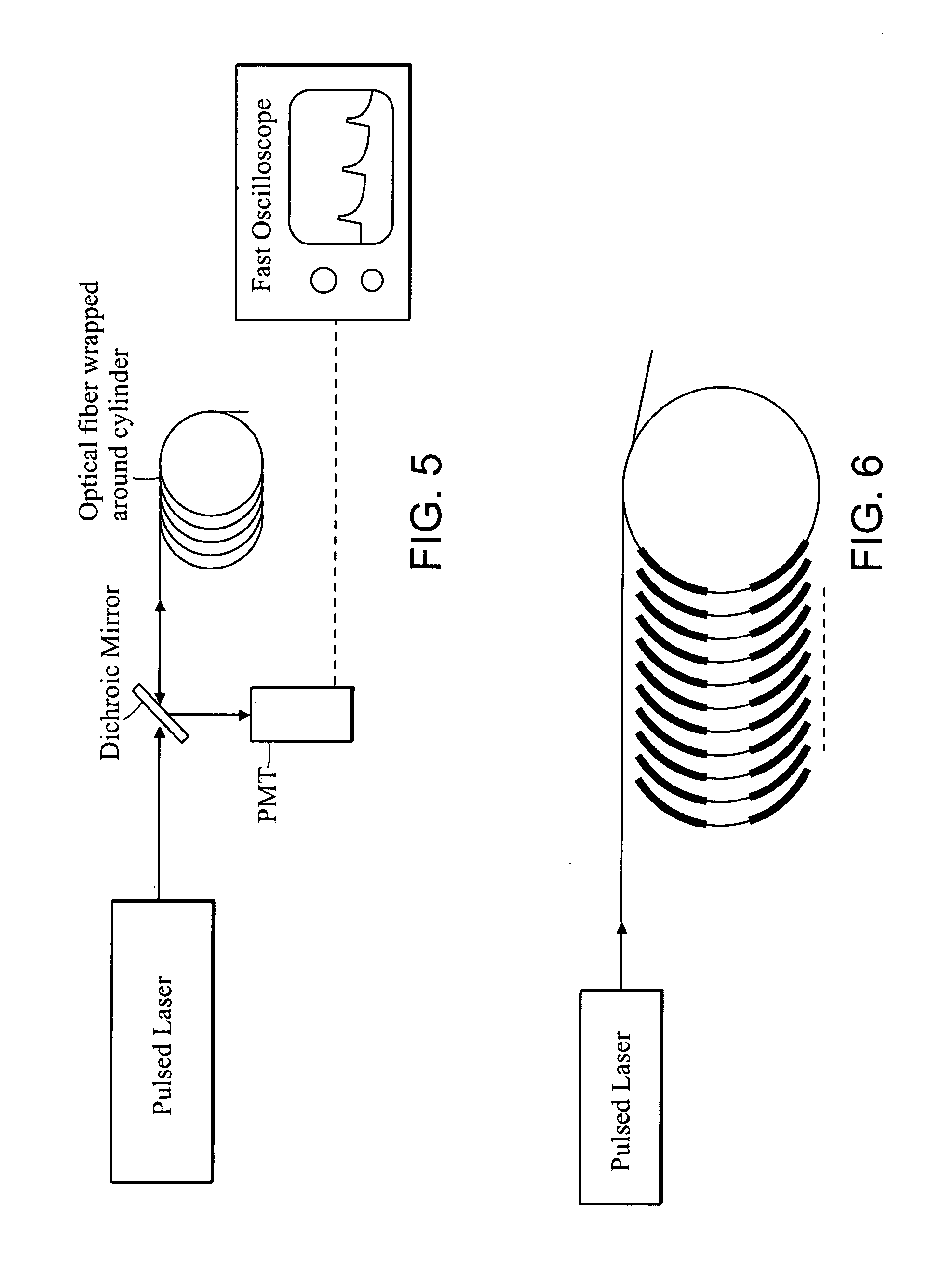
[0074]An experimental setup using the two fiber scheme as described supra is shown in FIG. 17. Two optical fibers were provided—a detection fiber, which is coiled around a cylinder, and an excitation fiber. Both fibers were multimode with 400 μm diameter silica cores (3M / Thorlabs FT-400-UMT). The TECS cladding was removed with acetone at certain regions along the fiber. The coiled detection fiber was stripped of the buffer and the cladding for a length of about 1 cm every 3.26 m. The separation of 3.26 m between adjacent regions was chosen such that the exposed core regions could be lined up parallel to the axis of the cylinder. The excitation fiber, whose buffer and cladding were also removed, was brought into direct contact with all of the exposed cores of the detection fiber. A total of six fiber-fiber connections were created.

[0075]Solutions of fluorophores were put on the fiber-fiber contacts. The regions were coated as follows:

[0076]Region 1 was coated with paraffin wax....


PUM

PropertyMeasurementUnit
fluorescence lifetimesaaaaaaaaaa
lengthaaaaaaaaaa
diameteraaaaaaaaaa

Abstract

Linear arrays of chemosensors or chemical compounds are supported by an optical fiber that allows one to rapidly assay the entire array using changes in optical properties such as fluorescence. The location of the agent along the fiber determines the identity of the agent in these linear arrays. Combinatorial libraries may be constructed on the fiber as well as assayed on the optical fiber. A system and method of analyzing the entire array of agents on an optical fiber using a light source, an optical fiber, and a detector are also described. The time delay between the excitation and detection determines the location being assayed along the fiber and therefore the identity of the agent being assayed. The present invention may find uses in the medical, pharmaceutical, environmental, defense, and food industries.

Description

GOVERNMENT SUPPORT[0001]The work described herein was supported, in part, by grants from the National Science Foundation (CHE-9726030). The United States government may have certain rights in the invention.PRIORITY INFORMATION[0002]This application claims priority to the application U.S. Ser. No. 09 / 253,153, filed Feb. 19, 1999 now abandoned, which claims priority to provisional application U.S. Ser. No. 60 / 075,629, filed Feb. 21, 1998. Both of these application are incorporated herein by reference.BACKGROUND OF THE INVENTION[0003]Chemosensors are used in a wide variety of measurements, from assaying components of a bodily fluid in a doctor's office to locating explosives in an airport. Arrays of sensors are of great utility, as they allow the detection of a large number of different species, or the high fidelity recognition of analytes using a large number of sensors of low selectivity. Data from a large array of chemical sensors can be analyzed to detect the presence or activity o...

Claims


Application Information

Patent Timeline
Patent Type & Authority Patents(United States)
IPC IPC(8): G01N33/53C12M1/34C40B40/10G01N21/64B01J19/00G01N21/77G01N33/566G01N37/00
CPCB01J19/0046G01N21/7703B01J2219/00515B01J2219/00538B01J2219/00596B01J2219/00657B01J2219/00707B01J2219/0072B01J2219/00725C40B40/10
Inventor SCHWABACHER, ALAN W.GEISSINGER, PETER
Owner UMW RES FOUND INC
Why Eureka
Try Eureka