
Method for the production of nitric acid

a technology of nitric acid and process, applied in the direction of electrical equipment, steam engine plants, inorganic chemistry, etc., can solve the problems of reducing the overall thermal efficiency, and reducing the thermal efficiency of the second step compared, so as to increase the electric power production

Inactive Publication Date: 2007-08-21
UHDE GMBH
View PDF19 Cites 7 Cited by
  • Summary
  • Abstract
  • Description
  • Claims
  • Application Information

AI Technical Summary

Benefits of technology

[0014]But if the expansion is split up into two steps, each of them being fed with heat, the overall thermal efficiency can decrease only. When viewing a thermodynamic loop cycle which operates at a pressure pm set in the range of p1 and p2, part of the heat being input, the formula η=1−(p1 / p2)n only applies to the first expansion step whereas the second step is subject to η=1−(p1 / pm)n, where p1 / pm exceeds p1 / p2. This lower pressure ratio acting on the second expansion step, hence, reduces the thermal efficiency of the second step compared to that of the first step. Hence, the said reduction of the overall efficiency applies to any such total. This analogously applies to any multi-step expansion.
[0020]If a steam turbine already exists, for example, in the case of revamping an existing state-of-the art plant, it is also possible to exploit such a steam turbine additionally for the generation of electric power and to substantially increase the electric power production.

Problems solved by technology

This is a very astonishing fact as the splitting up of one expansion step into several steps inevitably leads to a reduction of the thermal efficiency of said expansion, in particular if an intermediate heating takes place.
But if the expansion is split up into two steps, each of them being fed with heat, the overall thermal efficiency can decrease only.
This lower pressure ratio acting on the second expansion step, hence, reduces the thermal efficiency of the second step compared to that of the first step.

Method used


Image

  • Method for the production of nitric acid
  • Method for the production of nitric acid

Examples


Embodiment Construction

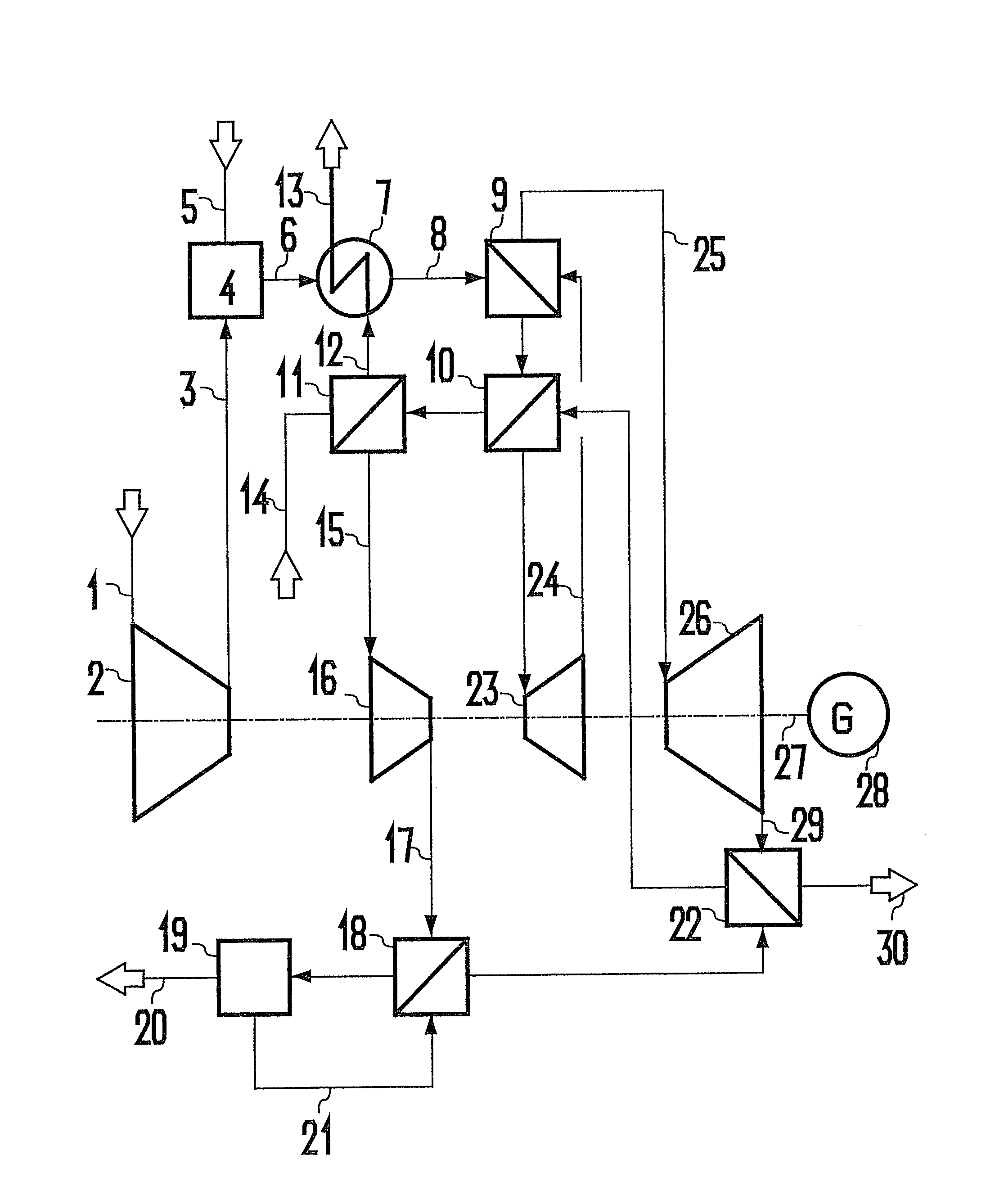
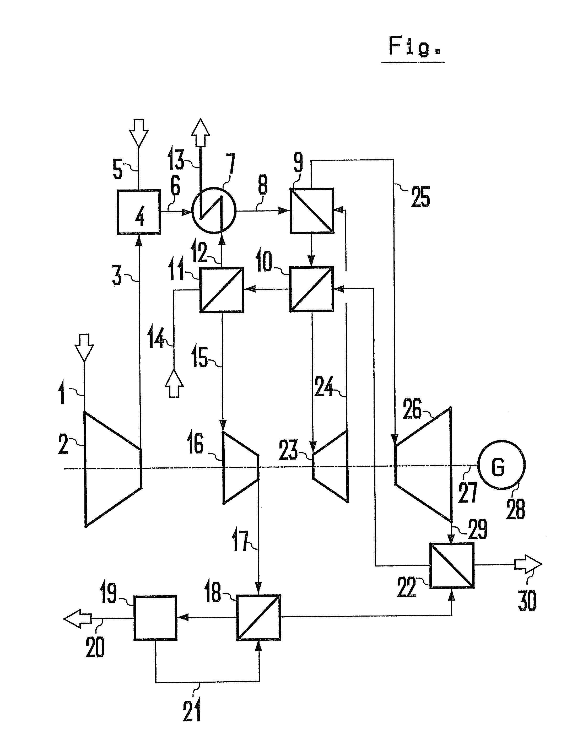
[0022]Air (1) is compressed in pre-compression unit (2) and a part stream thereof is fed as combustion air (3) to the catalytic combustion unit (4) in which it is burned together with ammonia (5) so that NO rich gas (6) is obtained at a temperature of about 900° C. This NO rich gas (6) is first slightly cooled in partial evaporator / superheater (7), the NO rich gas (8) is then exploited in the gas / gas heat exchangers (9 and 10) for heating the tail gas (see below) and finally cooled in partial evaporator / economiser (11). A mixture of water / steam (12) is first produced from feed water (14) in partial evaporator / economiser (11) and said mixture is subsequently used in the partial evaporator / superheater (7) to produce superheated steam (13). The cooled NO rich gas (15) undergoes a secondary compression in NO compression unit (16). The secondary compressed NO gas (17) is cooled in gas / gas heat exchanger (18) and converted to nitric acid (20) in absorption unit (19).

[0023]Tail gas (21) al...


PUM

PropertyMeasurementUnit
temperatureaaaaaaaaaa
inlet temperatureaaaaaaaaaa

Abstract

The invention relates to a method for the production of nitric acid having a concentration of between 50 and 76%, from ammonia and gas containing oxygen, under pressure, according to a single pressure method or dual pressure method. The expansion of the residual gas takes place in at least two stages in a work efficient manner. At least one device for heating the previously expanded gas to a temperature of more than 450° is disposed between every other expansion stage, using waste heat from the production process of nitric acid.

Description

BACKGROUND OF THE INVENTION[0001]The invention relates to a particularly economic process for the production of nitric acid with an approx. content of 50 to 76%, said process using the combustion of ammonia under pressure with the aid of an oxygen-bearing gas, in particular air, thereby simultaneously exploiting the reaction heat for the recovery of useful energy made available as steam or electric power.[0002]Nitric acid with a concentration of 50 to 76 percent is normally produced in plants using the Ostwald process as described, for instance, in the paper “Inorganic oxygen compounds” published by Mundo / Weber, Carl Hanser Publishing House in Munich and Vienna, 1982, a special print extracted from “Winnacker / Küchler” Chemische Technologie, volume 2, Inorganic Technology I, 4th edition, and in WO 01 / 68520 A 1.[0003]According to said technology there are a mono-pressure and a dual pressure process. The monopressure processes first provide for a compression of the air to medium pressu...

Claims


Application Information

Patent Timeline
Patent Type & Authority Patents(United States)
IPC IPC(8): C01B21/24C01B21/26C01B21/38C01B21/40C01B21/44C01B21/46H02P9/04
CPCC01B21/26C01B21/28F01K23/064Y02P20/129
Inventor DZIOBEK, FRANKCLAES, DETLEVJOHANNING, JOACHIMMAURER, RAINERSZONN, ERICH
Owner UHDE GMBH
Learn More