Magnetoresistive element with oxide magnetic layers and metal magnetic films deposited thereon

a magnetoresistive element and oxide technology, applied in the field of magnetic recording/recreation, can solve the problems of amorphous or microcrystal structure or heterogeneous crystal structure, difficult to laminate thin metal films such as ferromagnetic metal layers and high-polarized oxides for fabricating magnetoresistive elements, and deterioration in properties, so as to achieve sufficient reproducibility output, prevent noise from occurring, and narrow width

Inactive Publication Date: 2007-09-04
HITACHI GLOBAL STORAGE TECH JAPAN LTD
View PDF24 Cites 4 Cited by
  • Summary
  • Abstract
  • Description
  • Claims
  • Application Information

AI Technical Summary

Benefits of technology

[0015]The objective of the present invention is to provide a magnetic recording device with high long-term reliability, which has an ability of high-density recording, or a magnetic head using a magnetoresistive element. More specifically, the objective of the present invention is to achieve a spin valve type of magnetoresistive element with a high MR ratio, which has a ferromagnetic compound layer made from any of materials such as oxide material with a high-polarization disposed at the interface with a non-magnetic layer to provide the magnetic recording / reproducing device employing the element.
[0020]By heat treating the Fe—O layer, which has a crystal structure wherein oxygen atoms are exclusively dissolved in Fe in an amorphous or microcrystal state as deposition, at an appropriate temperature of 200-400° C., the composition close to the binary Fe—O system in the equilibrium state, that is, a phase with a high-polarization to allow the magnetoresistance to change by inducing the phenomenon of crystal precipitation in the direction near to the binary Fe—Fe3O4 phases can be formed in the layer. The use of above-mentioned manufacturing method and composition not only enables the high-polarized layer with good crystallinity, and in particular, the magnetite-containing layer to be formed, but also to reduce the ferromagnetic coupling field, a so called interlayer coupling field, generated between the ferromagnetic pinned layer and the soft magnetic free layer.
[0022]The thickness of the high-polarized layer can be made 0.5 nm or more to improve the rate of resistance magnetization and the thickness below 5 nm make the soft magnetic property better with an effect that the interlayer coupling field is reduced. In particular, the thickness, any of a range 1-3 nm, is preferable because both of higher MR ratio and reduced interlayer coupling field can be achieved.
[0025]The magnetoresistive element may have a single magnetic domain structure to prevent noise from occurring by making the soft magnetic free layer into the single domain magnetic structure. For example, the hard magnetic film, which has residual magnetization at its ends along the film surface of the magnetoresistive element and perpendicular to the orientation of magnetic field to be sensed, is disposed. Alternatively, the single magnetic domain is achieved by disposing, for example, the hard magnetic film having residual magnetization adjacent to the magnetoresistive element along its film thickness to form the same shape of ends on the hard magnetic film and the multi-layered composition of the magnetoresistive element.
[0026]According to the present invention, in the magnetoresistive element using the materials and composition, and in the magnetic recording / reproducing device with the magnetoresistive element incorporated in the reproducing part, high-density recording, that is, recording with short recording wavelengths, which are written on the recording medium, and narrow widths of recording tracks, is achieved, enabling sufficient reproducing output to ensure better recording.
[0027]As mentioned above, according to the present invention, a magnetoresistive element with a better bias property and high output power and a magnetic head using it can be achieved and in particular, the magnetic head and a high recording-density of magnetic recording / reproducing device with a better reproducing output and bias property can be achieved.

Problems solved by technology

Alternatively, the method for increasing magnetoresistance by applying a material of high-polarization has been also proposed but it is very difficult to laminate thin metal films such as ferromagnetic metal layers and the compounds such as the high-polarized oxide for fabricating the magnetoresistive element.
This is due to the problems that alternately laminating the high-polarized material usually composed of compounds such as oxides with metal layers may cause the high-polarized material to react to the metal layers, or may cause constituents of the material to diffuse in the metal layers to form a non-stoichiometric composition, resulting in deterioration in properties.
Further, when the thin films are laminated using the conventional film formation technique, such a problem is encountered that an amorphous or microcrystal structure or a heterogeneous crystal structure is formed.
500° C. Film formation, however, at such a higher temperature of the substrate not only makes it difficult to continuously form other metal layers and disturbs formation of ultra thin flattened metal layers, but also significantly accelerate the reactions between the high-polarized layers and other metal layers, for example, CoFe layers, interfering with formation of preferable high-polarized layers.
Thus, it is practically very difficult to laminate the magnetoresistive film with high-polarized layers and metal layers deposited.

Method used


Image

  • Magnetoresistive element with oxide magnetic layers and metal magnetic films deposited thereon
  • Magnetoresistive element with oxide magnetic layers and metal magnetic films deposited thereon
  • Magnetoresistive element with oxide magnetic layers and metal magnetic films deposited thereon

Examples


embodiment 1

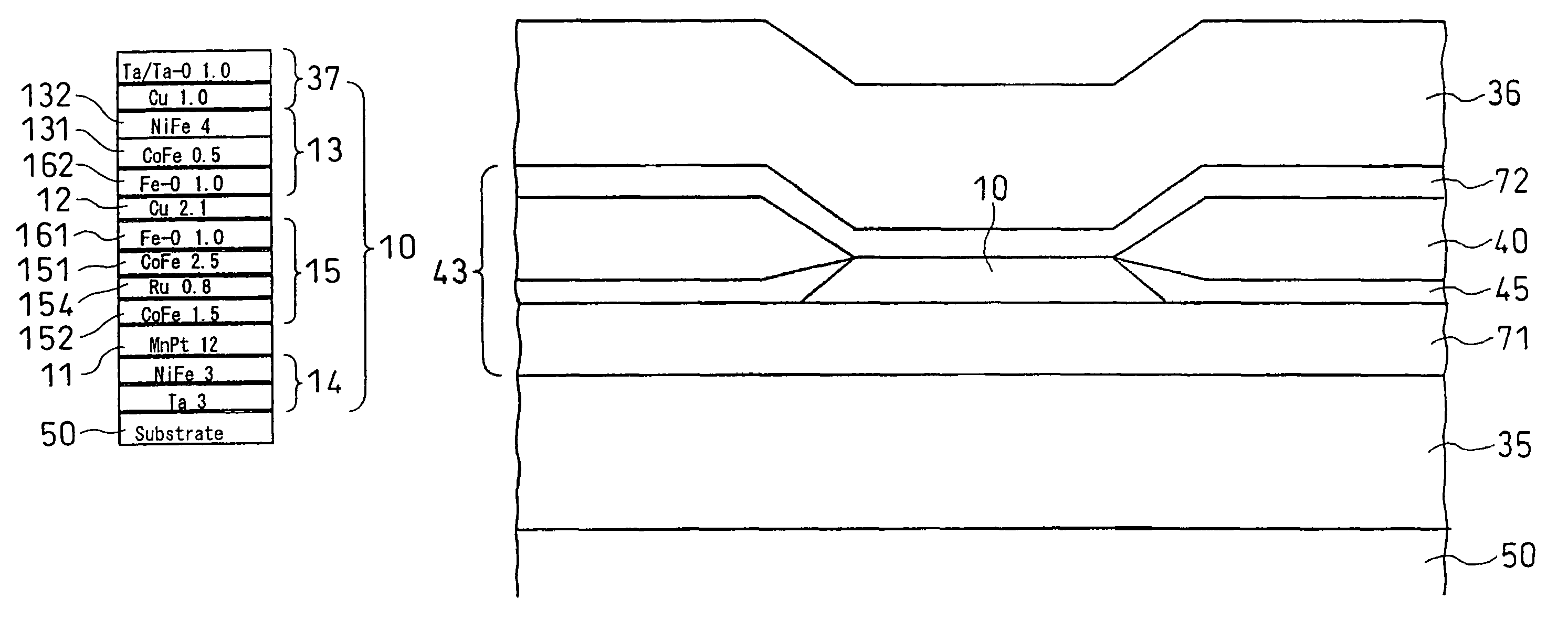
[0045]A thin film making up a giant magnetoresistive element multi-layered film according to the present invention is fabricated by radio-frequency magnetron sputtering equipment as described below. In the atmosphere, in which 1-6 mm Torr of argon is present, the materials described below are sequentially laminated on a ceramic substrate with a thickness of 1 mm to form the thin film. Tantalum, nickel-20 at % iron alloy, cupper, cobalt, MnPt, ruthenium, and Fe3O4 (magnetite) are used for sputtering targets. One square cm of Fe and Ni chips are appropriately disposed on a Co target for adjusting the composition. Similarly, one square cm of, for example, Fe chips are disposed on the magnetite target for adjusting the composition.

[0046]Hereafter, the composition with the Fe—O layer formed is expressed by the total amount of magnetite (Fe3O4) plus Fe, for example, the expression Fe10 at % in the Fe—O layer means Fe3O4 90 at %-Fe10 at %.

[0047]To sequentially form individual layers of the...

embodiment 2

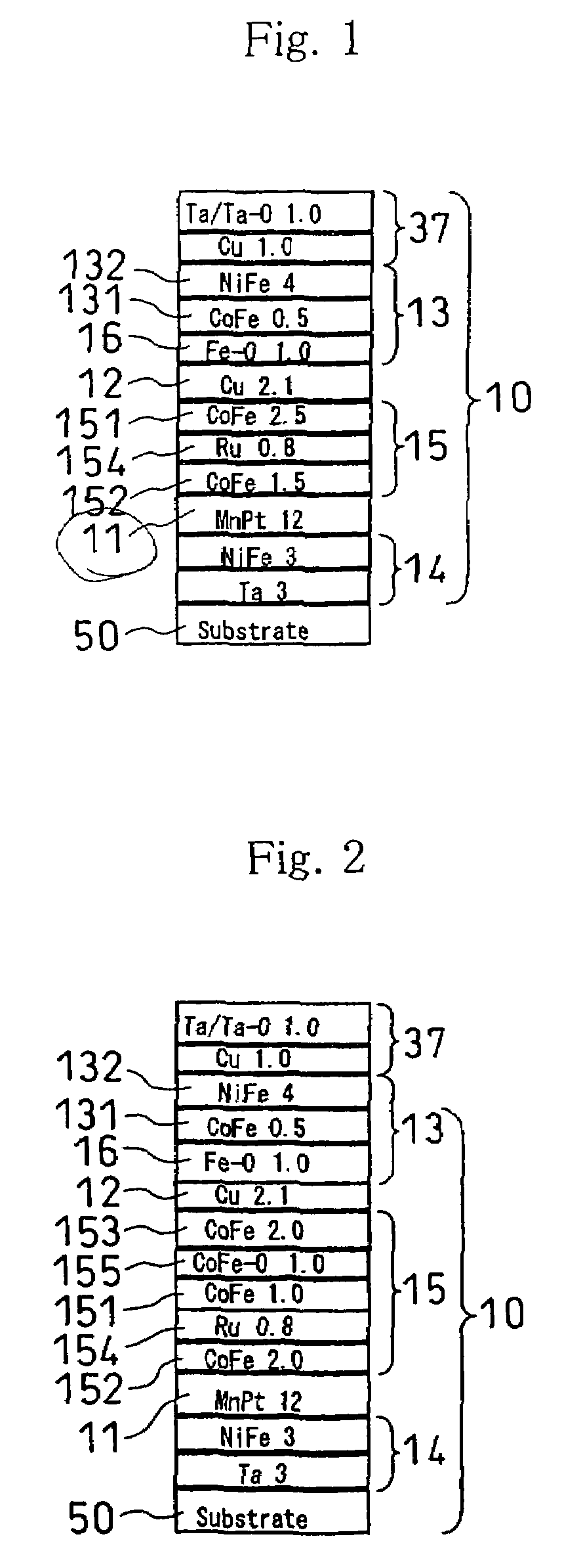
[0054]Similarly, FIG. 2 shows another example composition of the magnetoresistive multi-layered film to be used for the magnetoresistive element according to the prevent invention. The notation in the figure is the same as that of FIG. 1. The magnetoresistive multi-layered film 10 is formed by continuously laminating the underlayer film 14, antiferromagnetic film 11, ferromagnetic pinned layer 15, non-magnetic intermediate layer 12, the soft magnetic free layer 13, and the protective film 37 on the substrate 50. With respect to the multi-layered composition, electric resistance varies with the angle defined between the magnetization orientation of the ferromagnetic pinned layer 15 and that of the soft magnetic free layer 13 by means of giant magnetoresistance or tunnel magnetoresistance. Since the compositions and effects of the underlayer film 14 and the like, the soft magnetic free layer 13, and the like are the same as those shown in FIG. 1, their descriptions are omitted. If the...

embodiment 3

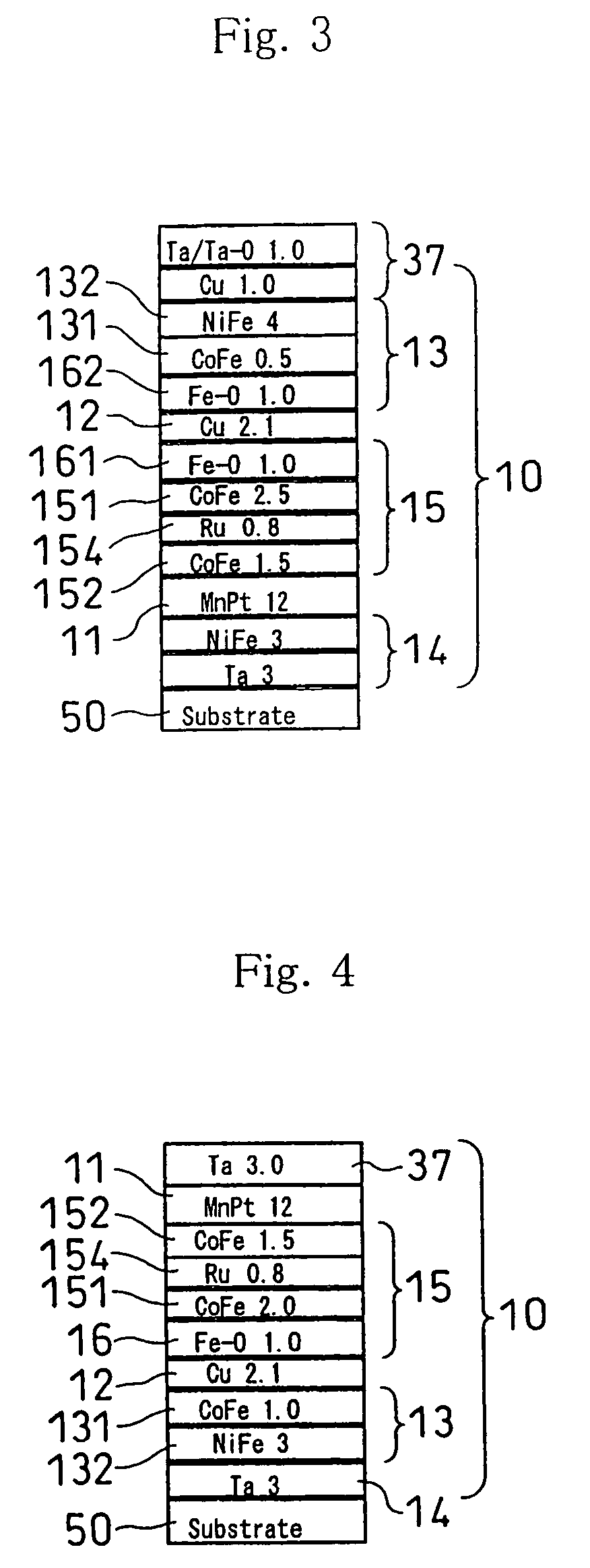
[0058]FIG. 3 is the view showing a further another example of the magnetoresistive multi-layered film to be used for the magnetoresistive element of the present invention. The notation in the figure is the same as that shown in FIG. 1. The magnetoresistive multi-layered film 10 is formed by continuously laminating the underlayer film 14, the antiferromagnetic film 11, ferromagnetic pinned layer 15, non-magnetic intermediate layer 12, the soft magnetic free layer 13, and the protective film 37 on the substrate 50.

[0059]With respect to the multi-layered composition, electric resistance varies with the angle defined between the magnetization orientation of the ferromagnetic pinned layer 15 and that of the soft magnetic free layer 13 by means of giant magnetoresistance or tunnel magnetoresistance. Since the compositions and effects of the underlayer film 14 and the like are the same as those shown in FIG. 1, their descriptions are omitted. If the composition of the underlayer film 14 or...


PUM

PropertyMeasurementUnit
thicknessaaaaaaaaaa
thicknessaaaaaaaaaa
temperatureaaaaaaaaaa

Abstract

No related magnetoresistive multi-layered films made from a metal magnetic film provide sufficient reproducing output power. A high-polarized layer with a thickness of 10 nm or less is formed as a Fe-rich Fe—O layer in contact with the interface of a non-magnetic intermediate layer and the resulting layers are heat treated to form a multi-layered film of ferromagnetic Fe—O layers, achieving a magnetoresistive element having high magnetoresistance.

Description

CROSS-REFERENCE TO RELATED APPLICATIONS[0001]This application is a Divisional of U.S. application Ser. No. 10 / 194,308 filed Jul. 15, 2002, now abandoned, and claims priority to U.S. application Ser. No. 10 / 194,308 filed Jul. 15, 2002, which claims priority to Japanese Patent Application No. 2001-216125 filed on Jul. 17, 2001, all of which are hereby incorporated by reference.FIELD OF THE INVENTION[0002]The present invention generally relates to magnetic recording / reproducing, and more particularly to a magnetic head suitable for a high-recording density magnetic recording / reproducing device and a magnetoresistive element to be used for it, and to its manufacturing method.BACKGROUND OF THE INVENTION[0003]A spin-valve magnetoresistive sensor using a multi-layered antiparallel pining layer and an antiferromagnetic exchange layer are disclosed in JP-A No.16929 / 1997. A spin-valve sensor using an antiferromagnetic coupling film is disclosed in JP-A-169026 / 1995. A magnetoresistive element ...

Claims


Application Information

Patent Timeline
Patent Type & Authority Patents(United States)
IPC IPC(8): G11B5/39G11B5/33G11B5/127G01R33/09H01F10/193H01F10/30H01F10/32H01L43/08H01L43/12
CPCB82Y10/00B82Y25/00G01R33/093G11B5/3903H01F10/324H01F10/3254H01F10/3272H01L43/10H01F10/1936G11B2005/3996H01F10/3295H10N50/85
Inventor HOSHIYA, HIROYUKISOEYA, SUSUMUMEGURO, KENICHI
Owner HITACHI GLOBAL STORAGE TECH JAPAN LTD
Why Eureka
Try Eureka