
Low complexity equalizer for radio receiver

a radio receiver and low complexity technology, applied in diversity/multi-antenna systems, pulse manipulation, pulse techniques, etc., can solve the problems of interference changing from destructive to constructive, interference can be reduced, and the frequency of the radio communication system is often affected by multi-path propagation effects, etc., to achieve better interference rejection, reduce the calculation load, and improve the effect of performan

Inactive Publication Date: 2007-09-04
ST ERICSSON SA
View PDF14 Cites 9 Cited by
  • Summary
  • Abstract
  • Description
  • Claims
  • Application Information

AI Technical Summary

Benefits of technology

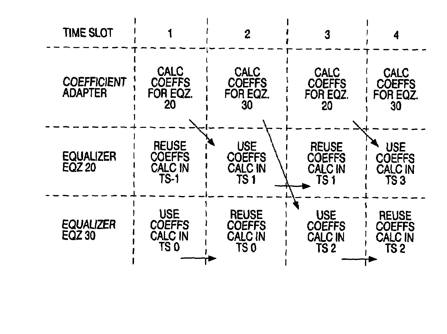
[0016]By sharing one adapter for adapting the coefficients between two or more equalizers, the calculation load can be reduced. This is particularly useful for small mobile terminals powered by battery. It can be applied to any type of equalizer, and using any manner of time sharing. The combiner can exploit any type of diversity between the equalized signals, and can be used with any type of radio modulation. It is based on a recognition that the primary type of interference addressed, multiple access interference, changes sufficiently slowly that it is not necessary to update the coefficients as frequently as the sample time for updating the output of the equalizer. It can give improved performance relative to known rake receivers in terms of better interference rejection (leading to increased network capacity) with good fading effect attenuation owing to the combining of (leading to improved efficiency for the network). These can be achieved with lower computational complexity compared to 2D-rake receivers, which means lower power consumption, which is of course particularly important for receivers in small mobile terminals.
[0027]Another aspect of the invention provides a method of offering a communication service using the terminal. This is claimed explicitly again as the advantages of the terminals can enable correspondingly improved services, with much greater added value than the value of the receiver component alone.

Problems solved by technology

Radio communication systems often suffer from the effects of multipath propagation also known as multipath fading, whereby a transmitted signal reaches a receiver via a plurality of distinct paths from the transmitter owing to the transmitted signal being scattered and reflected by numerous physical objects.
The receiver receives a superposition of these signals on the different paths, which can add up constructively or destructively, causing variations in the received signal amplitude.
If the mobile moves over a distance of the order of half a wavelength (which is 7.5 cm for 1,8 GHz) the interference may change from destructive to constructive or vice versa.
In a bad case, a receiver may stop receiving altogether at a particular location at which the received signal is in a deep fade.
Maintaining good communications can then become very difficult.
Diversity methods used in current mobile communications system are frequency and time diversity whereas space and polarisation diversity are not used (at least in receivers for mobiles) because of limitations on size, power consumption and processing capacity.
This condition is true in some environments (typically outdoor environment), in other environments of type such as indoor or pedestrian (i.e. Base Station outdoor and mobile indoor), the multipath gain is low and the rake performance rapidly degrades.
When τ>Tc (indoors or factory) the multipath diversity is null and the performance degrades rapidly.
However, orthogonality of spreading sequences is degraded or destroyed by the different delays caused by multipath propagation resulting in multiple access interference MAI at the output coherent rake receiver.
However as the number of users increases to a value approaching the spreading factor, it can have a catastrophic effect on performance even in perfect power control conditions.
This considerably increases the complexity in all situations and so is not practical for a mobile station for which low computational load, low power consumption and low cost are needed.

Method used


Image

  • Low complexity equalizer for radio receiver
  • Low complexity equalizer for radio receiver
  • Low complexity equalizer for radio receiver

Examples


Embodiment Construction

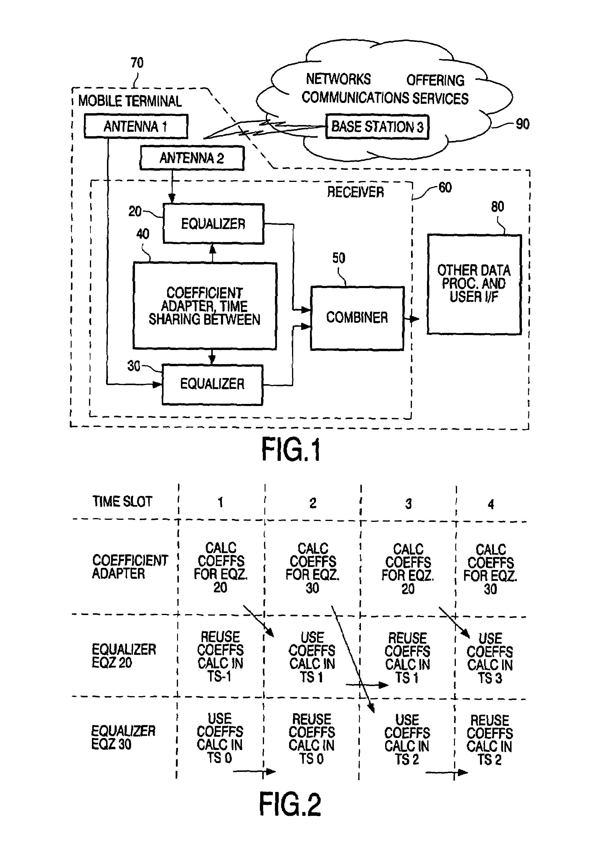
[0035]FIG. 1. Embodiment of a Receiver Coupled to Network.

[0036]FIG. 1 shows an embodiment of a receiver 60 coupled by a wireless link to a base station 3 of a network or networks 90. One particular application is for receiving data related to communications services offered by an operator over the network, such as voice services or information services for example. The receiver in this example is incorporated in a mobile terminal 70, though in principle it could be applied in a base station. The mobile terminal includes a pair of antennas 1,2, spaced and coupled to benefit from spatially diverse reception. Channel signals from the antennas feed the equalizers. In principle, the channel signals can be fed from a single antenna and exploit other types of diversity such as time or polarization for example. There can be more than two antennas and / or more than two channels. Other parts of the mobile terminal such as user interface, data or voice processing functions and so on are repres...


PUM


Abstract

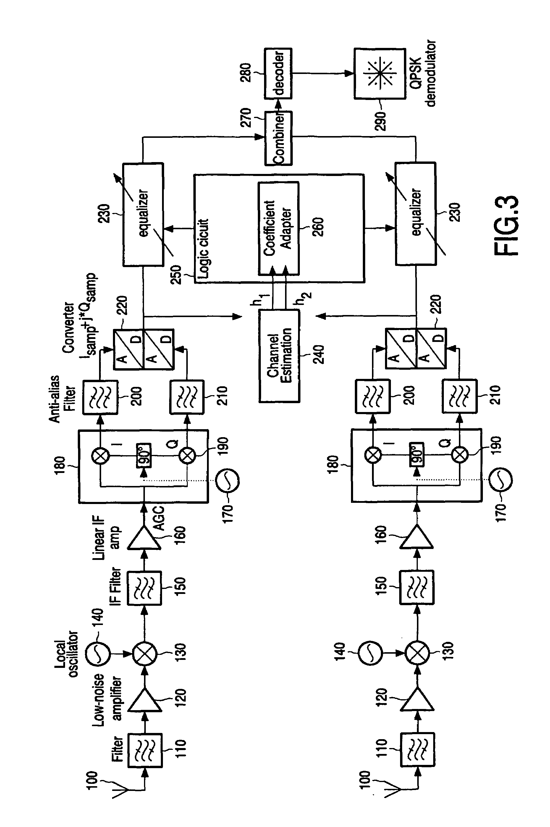
A diversity receiver (60) has two diverse channels fed by the antennas, an adaptive equalizer (20,30) for each channel and a coefficient adapter (40) for adapting two sets of coefficients in a time shared manner for the equalizers. A combiner combines the equalized signals. By sharing one adapter for adapting the coefficients between two or more equalizers, the calculation load can be reduced. This is useful for small mobile terminals powered by battery, for use with GSM or UMTS or other radio networks. It can be applied to any type of equalizer, and using any manner of time sharing. The combiner can exploit any type of diversity between the equalized signals. The equalizers can output two equalized signal values in consecutive time slots, by reusing the same coefficients, while new coefficients are being calculated.

Description

FIELD OF THE INVENTION[0001]The invention relates to diversity receivers, to mobile terminals having such receivers, and to methods of offering communications services using such terminals.BACKGROUND[0002]Radio communication systems often suffer from the effects of multipath propagation also known as multipath fading, whereby a transmitted signal reaches a receiver via a plurality of distinct paths from the transmitter owing to the transmitted signal being scattered and reflected by numerous physical objects. In mobile communication systems, the different paths and their relative signal strengths will change rapidly if the mobile terminal is moving. The receiver receives a superposition of these signals on the different paths, which can add up constructively or destructively, causing variations in the received signal amplitude. If the mobile moves over a distance of the order of half a wavelength (which is 7.5 cm for 1,8 GHz) the interference may change from destructive to construct...

Claims


Application Information

Patent Timeline
Patent Type & Authority Patents(United States)
IPC IPC(8): H04B7/00H04B1/707H04B1/7115H04B7/08
CPCH04B7/0845H04B7/08H04B7/005H04L1/02
Inventor DILOISY, ROMAIN
Owner ST ERICSSON SA
Learn More