Electric double layer capacitor

a double-layer capacitor and capacitor technology, applied in the field of electric double-layer capacitors, can solve the problems of reducing discharge energy, reducing charge-discharge efficiency, and simply optimizing the amount of electrolytic solution in the manner indicated in the above art, and achieves low internal resistance, excellent cycle characteristics, and high voltage rating.

Active Publication Date: 2007-09-11
TOC CAPACITA +1
View PDF19 Cites 14 Cited by
  • Summary
  • Abstract
  • Description
  • Claims
  • Application Information

AI Technical Summary

Benefits of technology

[0012]It is therefore an object of the invention to provide an electric double layer capacitor which has a high voltage rating, excellent cycle characteristics during high-current charging and discharging, and a low internal resistance in low-temperature environments.
[0013]We have found that, by controlling within a specific range the ratio between the theoretical amount of ions defined in terms of the rated capacitance C (farads) of the capacitor and the rated voltage V (volts), which is the maximum voltage allowed across the capacitor, and the amount of ions within the organic electrolytic solution which impregnates the positive and negative polarizable electrodes and the separator, the voltage rating of the capacitor can be increased without compromising the high-current charge-discharge characteristics and the cycle characteristics of the electric double layer capacitor, in addition to which the capacitor can also be provided with excellent low-temperature characteristics.
[0021]The invention makes it possible to obtain an electric double layer capacitor which has a high voltage rating, excellent high-current charge-discharge characteristics and cycle characteristics, and a low internal resistance in low-temperature environments.
[0022]Moreover, the electric double layer capacitor of the invention also has an excellent durability under high-voltage application, and excellent charge-discharge properties at low temperatures.

Problems solved by technology

Yet, merely optimizing the amount of electrolytic solution in the manner indicated in the above art is not sufficient for achieving an electric double layer capacitor with a higher voltage rating.
Because this leads to a decrease in the charge-discharge efficiency and a reduction in discharge energy during high-current charging and discharging, the result is a decline in the cycle characteristics.
Moreover, lowering the electrolyte concentration may lead to a marked increase in the internal resistance within a low-temperature environment, making charging and discharging impossible to carry out.

Method used


Image

  • Electric double layer capacitor
  • Electric double layer capacitor
  • Electric double layer capacitor

Examples


example 1

(1) Manufacture of Positive Electrode Assembly

[0093]A coating slurry for the positive polarizable electrodes was prepared by mixing the activated carbon Maxsorb MSP20 (produced by Kansai Coke and Chemicals Co., Ltd.; BET specific surface area, 2,300 m2 / g; pore volume, 1.07 mL / g; 50% particle size, 9.5 μm), a conductive material (HS-100; Denki Kagaku Kogyo KK), and PVDF (Sigma-Aldrich Japan KK; weight-average molecular weight, 534,000) as the binder in a weight ratio therebetween of 85:8:7 within N-methylpyrrolidone (NMP) as the coating solvent.

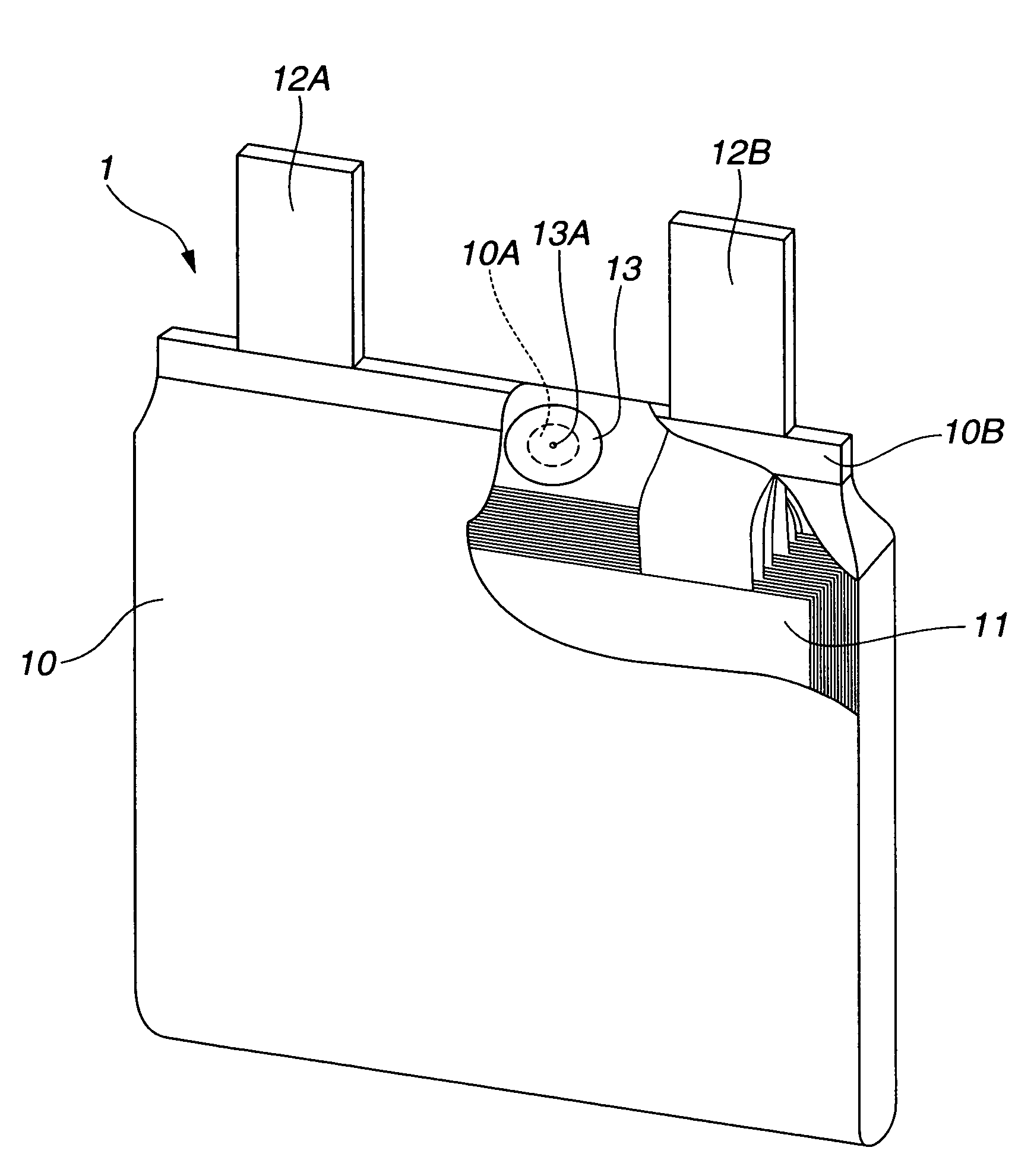
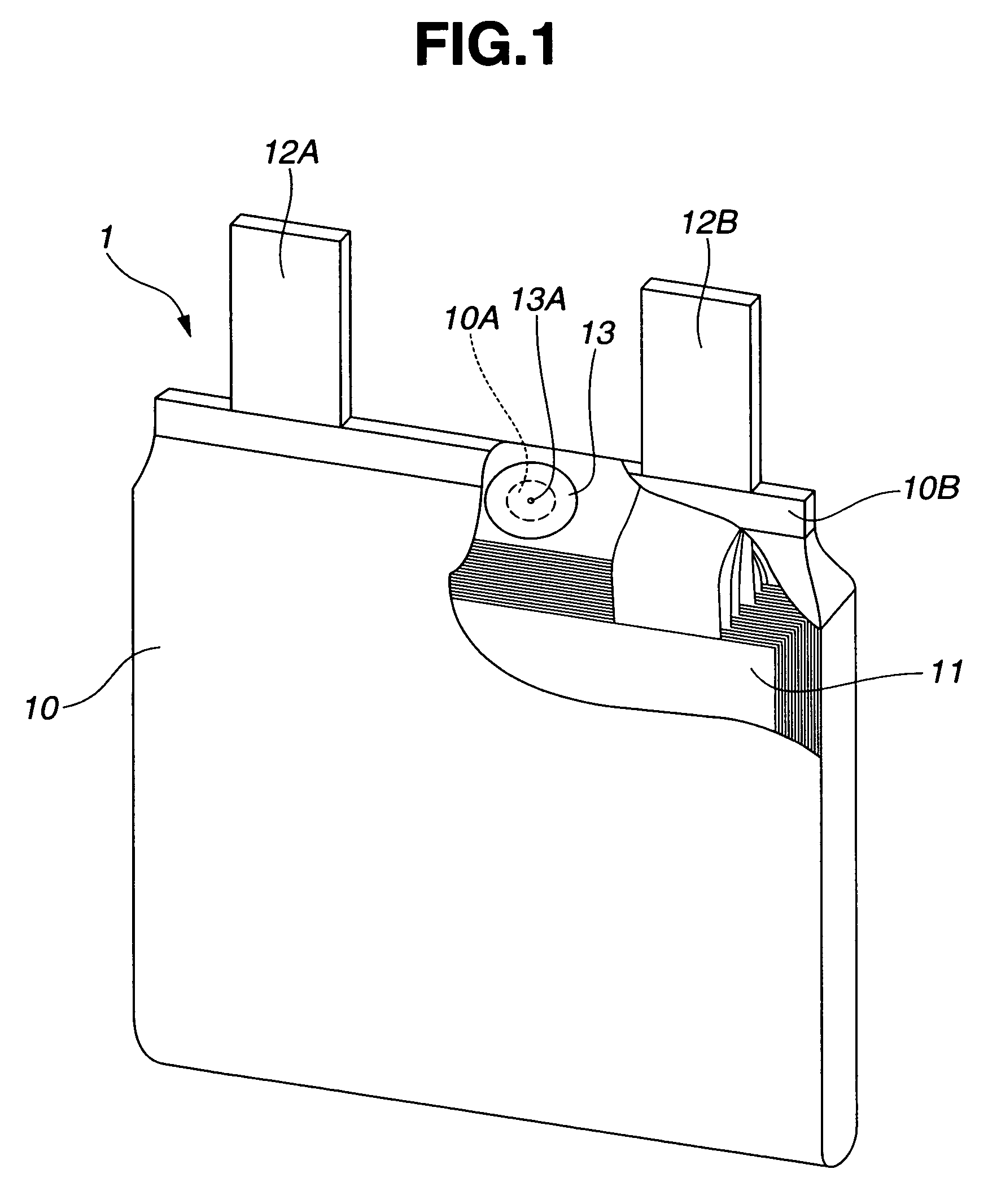
[0094]The slurry was applied to both sides of an etched aluminum foil (30CB; Japan Capacitor Industrial Co., Ltd.) as the positive current collector 111, then rolled using a roll press, following which the NMP was removed by drying so as to form positive polarizable electrodes 112, thereby giving a positive polarizable electrode assembly 11A. The apparent surface area of the polarizable electrodes 112 in this electrode assembly 11A was 130 cm2...

example 2

[0101]Aside from setting the thickness of the negative polarizable electrode formed on one side of the current collector to 85 μm and changing the amount the organic electrolytic solution added to 39 mL, an electric double layer capacitor was obtained in the same way as in Example 1.

example 3

[0102]Aside from setting the thickness of the negative polarizable electrode formed on each side of the current collector to 90 μm and changing the amount of the organic electrolytic solution added to 41 mL, an electric double layer capacitor was obtained in the same way as in Example 1.


PUM

PropertyMeasurementUnit
porosityaaaaaaaaaa
volume ratioaaaaaaaaaa

Abstract

An electric double layer capacitor is composed of a pair of current collectors, a positive polarizable electrode provided on one of the pair of current collectors, a negative polarizable electrode provided on the other of the pair of current collectors, a separator between the positive and negative polarizable electrodes, and an organic electrolytic solution which impregnates at least the positive and negative polarizable electrodes and the separator. The capacitor has a theoretical amount of ions Qt defined asQt (moles)=C×V÷96,500,wherein C is the rated capacitance (farads) of the capacitor and V is the rated voltage (volts), and an amount of ions Qe in the organic electrolytic solution, such that Qe / Qt=1.7 to 3.5. The capacitor has a high voltage rating, excellent cycle characteristics during high-current charging and discharging, and a low internal resistance in low-temperature environments.

Description

CROSS-REFERENCE TO RELATED APPLICATION[0001]This non-provisional application claims priority under 35 U.S.C. §119(a) on Patent Application No. 2005-277475 filed in Japan on Sep. 26, 2005, the entire contents of which are hereby incorporated by reference.BACKGROUND OF THE INVENTION[0002]1. Field of the Invention[0003]The present invention relates to an electric double layer capacitor.[0004]2. Prior Art[0005]To enhance the characteristics of electric double layer capacitors, the practice until now has been to adjust within a suitable range the volume ratio of the amount of electrolytic solution to the void volume of the polarizable electrodes and the separator.[0006]For example, JP No. 3008399, JP-A 2001-196273, JP-A 2002-93663, JP-A 2004-253562 and JP-A 2005-45180 report that electric double layer capacitors of an excellent durability and temperature characteristics and a low resistance can be obtained by controlling to a suitable value the volume ratio of the amount of electrolytic ...

Claims


Application Information

Patent Timeline
Patent Type & Authority Patents(United States)
IPC IPC(8): H01G9/00H01G11/26H01G11/58H01G11/62
CPCH01G9/038H01G9/155H01G11/26H01G11/62H01G11/58Y10T29/417Y02E60/13Y10T29/41H01G11/52
Inventor YOSHIDA, HIROSHIYUYAMA, KANAKO
Owner TOC CAPACITA
Why Eureka
Try Eureka