
Ion-optical phase volume compression

a technology of phase volume compression and ion-optical, which is applied in the direction of electron/ion optical arrangement, particle separator tube details, separation process, etc., can solve the problems of inability to reduce the phase volume of ions by such a reduction, heavy gases cannot be used, and no hyperbole system is used at all. to achieve the effect of facilitating production

Active Publication Date: 2007-10-02
BRUKER DALTONIK GMBH & CO KG
View PDF19 Cites 26 Cited by
  • Summary
  • Abstract
  • Description
  • Claims
  • Application Information

AI Technical Summary

Benefits of technology

The invention is a method for producing a fine, highly parallel ion beam by using a conditioning cell with an adjustable DC potential to decrease the phase volume of the ions and collect them by draining them out of the cell. The method can produce beams with almost monoenergetic ions and can also include a fragmentation step. The conditioning cell can be designed with longitudinal electrodes or a quadrupole system with individual adjustable potential gradients. The use of hyperbolic electrodes and a mixture of RF and DC voltages can help prevent ion losses and improve the efficiency of the process. The invention can be used in a continuous or discontinuous manner and can also include a collision cell for fragmentation.

Problems solved by technology

Conditioning the ions by reducing their phase volume like this cannot be achieved by ion-optical methods (a consequence of the Liouville theorem) and with the exception of the complicated method of laser cooling, only the gas cooling described can reduce the phase volume.
The fragmentation process in these quadrupole systems would proceed more effectively in collision gases with a heavier molecular weight; these heavier gases cannot be used, however, since their gas molecules deflect the ions more strongly to the side during collisions and it is then very easy for the ions, as a result of such collision cascades, to escape laterally out of the round-rod quadrupole system.
Inexpensive round-rod systems are still considered good enough for the collision chambers, expensive hyperbole systems are not used at all.
Round-rod systems contain octopole and higher even-numbered multipole fields of considerable strength superimposed on the quadrupole field, leading to a distortion of the ion oscillations in the radial direction and hence to the formation of overtones of the ion oscillation.
For ions lying damped in the axis of the system, the resonances are not effective.
In the most unfavorable case, even the selected parent ions are subjected to this resonance and disappear to a large extent from the collision cell.
Apart from this, round-rod systems have the further disadvantage that the pseudopotential wall between the rods is extremely low (for commercially available systems only some ten to twenty volts) and can easily be overcome by ions with an energy of 50 electron volts, usually the minimum energy required for fragmentation processes, by means of a random laterally-deflecting collision cascade.
In the case of a very light collision gas, the larger angles of deflection of a small number of collisions are no longer able to compensate statistically as well as the large number of smaller angles of deflection.
As far as the conditioning of the ions is concerned, a disadvantage of most collision cells is that either the ions leave the cell again with relatively high energy after sweeping through once, since their energy has not been sufficiently reduced by collisions, or that, after a sufficiently large number of collisions (after a long sweep at high pressure or also after several sweeps with reflections at the ion output) they have given up their kinetic energy apart from residues of thermal energy and then remain in the collision cell.
In addition, the resistance must not be particularly high, otherwise the RF alternating voltage cannot propagate along the wires sufficiently quickly.
It is therefore only possible to generate very low DC voltage drops along the wire.
These quadrupole systems are difficult to produce, however, and not very precise.
These arrays are, however, not completely satisfactory: partly because they are complicated to produce and therefore not particularly cheap, and partly because they function only moderately satisfactorily.
This system has only limited suitability for the fragmentation of ions since the fragmentation always scatters the ions as well, and the losses are therefore much too high.
System (f) comprising thin ceramic tubes (according to the description tube walls around 0.5 to 1 millimeter thick) with interior metal coating to generate the RF field, and exterior resistance layer for the DC voltage drop, has disadvantages: the RF frequency causes such high dielectric losses in the material of the ceramic tubes that the system becomes extremely hot within a very short time and practically glows in the vacuum.
The possible oscillation amplitudes for the ions are extremely limited, however; the ions can easily collide with the rods and be lost through discharge.
Multipole systems are therefore not as suitable as quadrupole systems for beam conditioning.
For some types of mass spectrometer, the higher multipole systems cannot therefore be used as a collision cell for the analysis of the daughter ions owing to their poor beam conditioning.
If no such correlation exists, however, i.e. if ion locations and ion transverse velocities are statistically distributed with no correlation between the two distributions, then it is no longer possible to achieve high mass resolution.

Method used


Image

  • Ion-optical phase volume compression
  • Ion-optical phase volume compression
  • Ion-optical phase volume compression

Examples


Embodiment Construction

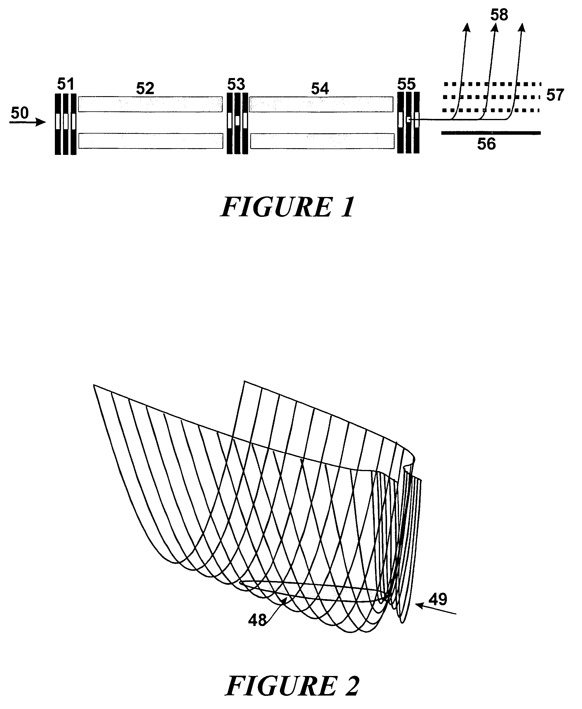
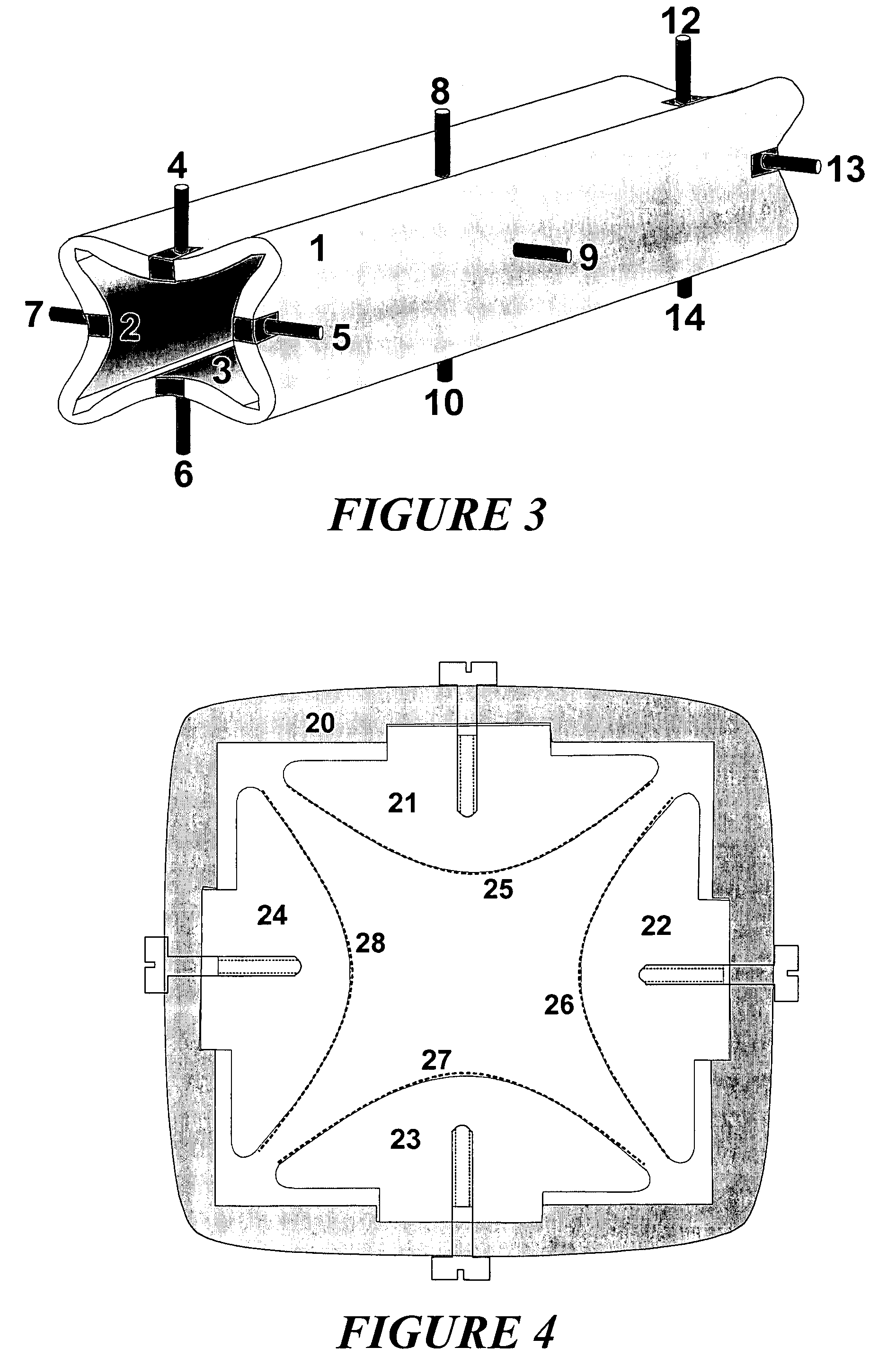
[0054]A preferred embodiment of the method for producing a fine ion beam with ions displaying homogeneous energies consists in using a hyperbolic quadrupole system which facilitates the generation of an axial potential gradient, roughly the quadrupole system (54) in FIG. 1, in conjunction with a diaphragm system (55) at the ejection end of the quadrupole system. The ions can be introduced through an injection diaphragm system (53) into the interior of the quadrupole system, for example. A glass quadrupole system (1) shown in FIG. 3 can be used as the quadrupole system, for instance. For this, the quadrupole system is filled with collision gas at a pressure of between 10−2 and 10+2 Pascal, causing the ions to thermalize more or less rapidly, i.e. they give up their kinetic energy to the collision gas keeping only thermal residual energies. The restoring forces of the pseudopotential cause the ions having lost their kinetic energy, to collect in the axis of the quadrupole system.

[0055...


PUM


Abstract

The invention relates to a method for damping the kinetic energy of ions in ion cells filled with collision gas and with an exit aperture to drain the ions out of the cell. The invention uses a conditioning cell with an adjustable DC potential which decreases towards the exit aperture to compress the phase volume of the ions by damping their kinetic energies, collecting the ions after thermalization in the spatial potential minimum thus created and letting them drain away relatively slowly through a central potential minimum in the exit aperture system. This facilitates the production of very fine, highly parallel ion beams which consist of almost monoenergetic ions. In particular, the method can also be coupled with a fragmentation of the ions.

Description

FIELD OF THE INVENTION[0001]The invention relates to a method for damping the kinetic energy of ions in ion cells filled with collision gas and with an exit aperture to drain the ions out of the cell.BACKGROUND OF THE INVENTION[0002]Some types of mass spectrometers, for example time-of-flight mass spectrometers with orthogonal ion injection, require a very well-conditioned ion beam for high mass resolution and precise mass determination. By a “well-conditioned ion beam” we mean here a beam of ions flying as parallel as possible with kinetic energies which are as uniform as possible. This “ion beam conditioning” can consist in first decelerating the motion of the ions in a conditioning cell by numerous collisions with a collision gas, drawing the decelerated ions out of the conditioning cell through suitable diaphragm systems, and then forming them into a relatively fine, almost parallel ion beam. The process of reducing the kinetic energy of the ions by decelerating them in a collis...

Claims


Application Information

Patent Timeline
Patent Type & Authority Patents(United States)
IPC IPC(8): H01J49/40H01J49/42B01D59/44G21K1/093H01J37/141H01J49/06H01J49/44
CPCH01J49/0481H01J49/443H01J49/062H01J49/06
Inventor WEISS, GERHARD
Owner BRUKER DALTONIK GMBH & CO KG
Learn More