
Data access arrangement using a high frequency transformer for electrical isolation

a high-frequency transformer and data access technology, applied in the field of isolation barriers, can solve the problems of large volume, increased size and cost, and bulky and expensive satisfactory voice band transformers for this type of electrical isolation, and achieve the effect of less power

Inactive Publication Date: 2007-10-02
ESS TECHNOLOGY
View PDF73 Cites 16 Cited by
  • Summary
  • Abstract
  • Description
  • Claims
  • Application Information

AI Technical Summary

Benefits of technology

[0011]We have observed that the linearity of a transformer largely depends on the magnetic inductance density in its magnetic core. The magnetic inductance density is directly proportional to the power delivered by the transformer, while inversely proportional to the volume of magnetic core, the number of turns of the transformer, and the frequency of the signal. In other words: the smaller the signal power, the larger the magnetic core, the more the coil turns, and the higher the signal frequency, the more linear the transformer. Or to achieve the same linearity, smaller signal power and higher frequency will result in a smaller magnetic core with fewer coil turns, leading to a smaller and less expensive transformer.
[0012]The current invention uses two approaches to achieve a low cost, reliable electrical isolation barrier using a single high frequency (HF) transformer. First, we can add an amplifier at the line side of The electrical isolation barrier to reduce the power requirement of the transformer.

Problems solved by technology

The primary source of distortion in a transformer is non-linearity, which causes signal harmonics.
Therefore, a high linearity requirement is placed on the voice band transformer, which generally increases its size and cost.
Because of these drawbacks a satisfactory voice band transformer for this type of electrical isolation is bulky and expensive.
However, a digital or pulse transformer is binary and therefore cannot carry two signals, the transmit signal and the receive signal, simultaneously.
However, this time division multiplexing method will destroy the self-clock ability of the signal.
Therefore the clock signal has to be carried by a different means, typically using another transformer and adding further expense to the product.
Another disadvantage of digital or pulse transformers is that they must be operated in their saturation range, requiring more power than similar transformers operated in their non-saturated (or “linear”) range.
Such a high voltage large capacitor is expensive.
However, this has the drawback of requiring an elegant method to compensate for the non-linearity of the optical couplers.
In the pass band approach, some means are used to modulate the signal to a higher frequency to reduce the impact of the non-linearity of the optical couplers, adding additional cost and complexity to the solution.

Method used


Image

  • Data access arrangement using a high frequency transformer for electrical isolation
  • Data access arrangement using a high frequency transformer for electrical isolation
  • Data access arrangement using a high frequency transformer for electrical isolation

Examples


Embodiment Construction

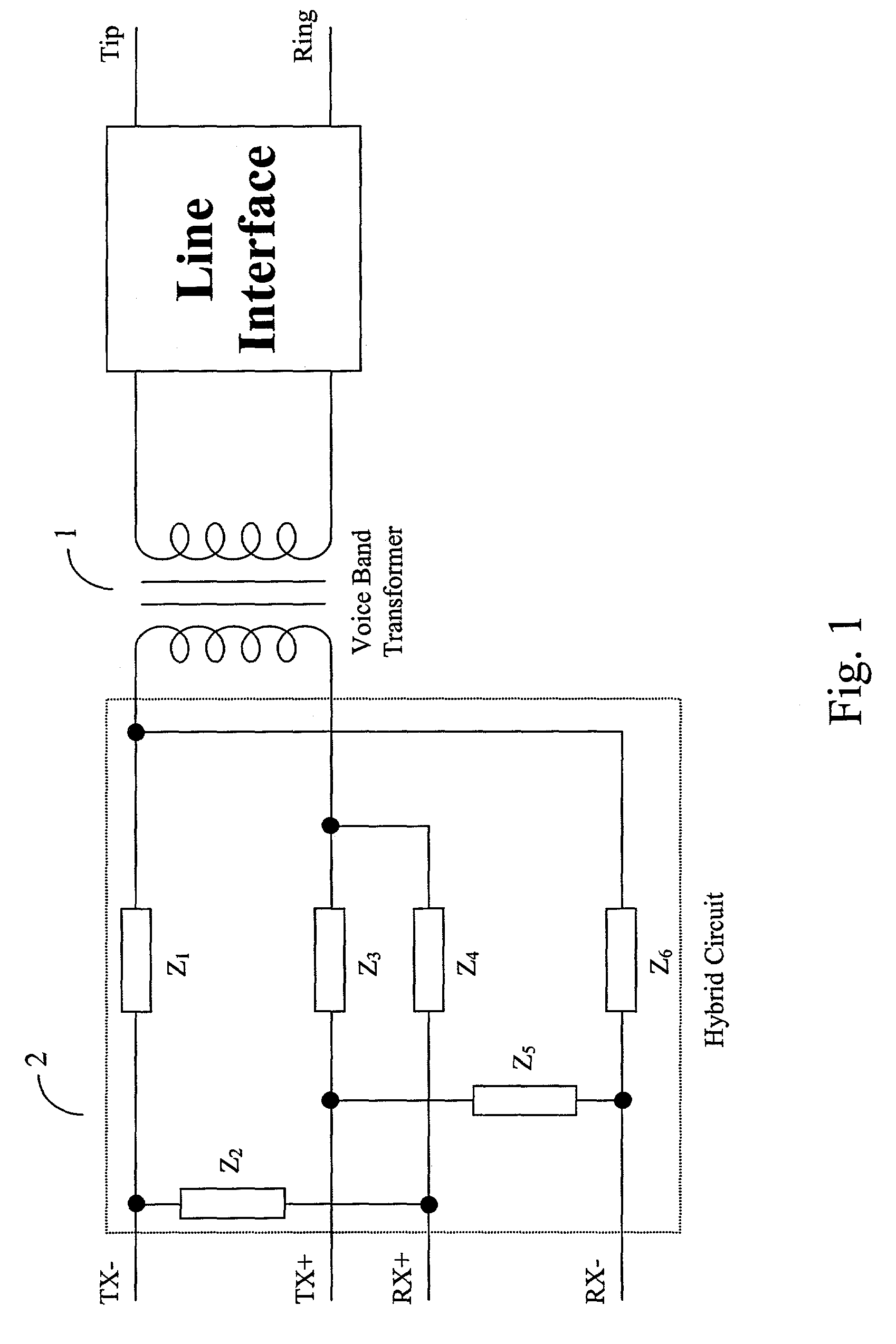
[0025]FIG. 1 illustrates a prior art isolation barrier for use in a DAA. In that figure, a modem uses a voice band transformer 1 in its DAA to provide The electrical isolation barrier. The transformer carries both the transmit signal and the receive signal. The separation of these two signals is done using a hybrid circuit 2 of a type used to couple four-wire to two-wire circuits. Hybrid circuits are well known in the art and have four sets of terminals arranged in two pairs designed to produce high loss between two sets of terminals of a pair when the terminals of the other pair are suitably terminated. The hybrid circuit illustrated in FIG. 1 contains six impedance elements Z1-Z6, which are typically realized using resistors, capacitors, or some combination thereof. Other hybrid circuit configurations are also possible in a conventional transformer DAA.

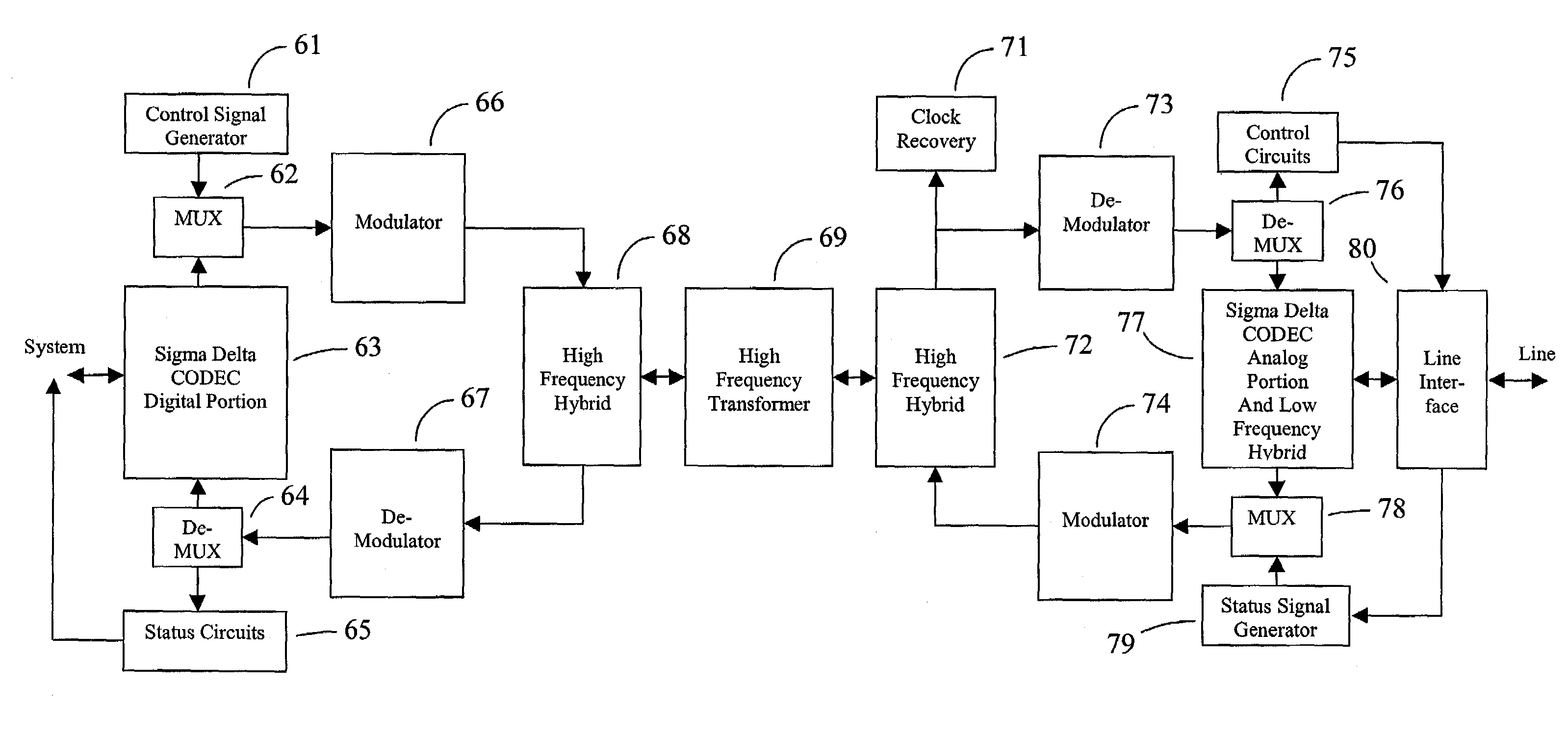
[0026]FIG. 2 illustrates our basic invention. In that figure, an HF transformer 24 provides isolation. An input signal 21, which m...


PUM


Abstract

An electrical isolation barrier for use in a Data Access Arrangement uses a high frequency (HF) transformer 24 to provide isolation. An input signal, which may be analog or digital, is connected to a modulator. The analog output of the modulator is connected to the input of the HF transformer. The output of the HF transformer is connected to the input of a demodulator. Simple amplitude modulation can be used in the modulator to modulate the input signal to the frequency range of operation of the HF transformer. A simple low pass filter may be incorporated in the demodulator to remove harmonic distortion caused by the HF transformer. The output signal of the demodulator is substantially the same as input signal.

Description

BACKGROUND OF THE INVENTION[0001]The invention relates to isolation barriers for selectively isolating electrical circuits from each other. Such isolation barriers find use in modems and other devices, particularly those that require electrical isolation barriers between the devices and the public telephone network.[0002]The Federal Communications Commission Part 68 has mandated that electrical connections to the public telephone network provide an isolation barrier between circuitry directly connected to that network (called the “line side” circuitry) and circuitry, such as a modem, that is directly connected to residential power (called the “system side” circuitry.) This isolation barrier must provide isolation such that a large magnitude voltage source of one thousand volts or fifteen hundred volts at 50 Hz or 60 Hz rms applied between various points on the device causes no more than 10 milliamperes leakage current.[0003]The theory of isolation barriers is well known in the prior...

Claims


Application Information

Patent Timeline
IPC IPC(8): H04B3/00H04L25/00H01FH04B3/03H04J3/04H04L25/02
CPCH04L25/0268H01F2019/085
Inventor DONG, PINGCOOKMAN, JORDAN C.
Owner ESS TECHNOLOGY
Learn More