Assembled cathode and plasma igniter with such cathode

Inactive Publication Date: 2007-10-16
YANTAI LONGYUAN POWER TECH
View PDF22 Cites 16 Cited by
  • Summary
  • Abstract
  • Description
  • Claims
  • Application Information

AI Technical Summary

Benefits of technology

[0011]Since the combined type cathode adopts high-velocity nozzle with forced cooling, the heat transmission of the cathode is accelerated and the life of the cathode is lengthened. The life of the cathode is further improved through adopting good electrically conductive and good thermally conductive material, preferably Ag-based material as cathode plate.
[0012]Through adopting the composite anode, the flow field of the plasma in the inner cavity of the anode is changed. In particular, at the nozzle, the axial component of the flow is dominant, and thus the anode is prevented from being contaminated by the pulverized coal. In addition, since the receiving area of the anode is increased on the basis of the conventional nozzle, the electrons are received within the anode nozzle tube, and thus will not be disturbed by any external dynamic field, and thus the output power of the equipment is very stable. The arc-transporting coil coated outside of the composite anode increases the length of the plasma flame, and thus improve the ability of igniting the pulverized coal.
[0013]Furthermore, adopting multi-stage axial powder delivery and gas film cooling techniques, and performing ignition through stage-by-stage amplification, which increase greatly

Problems solved by technology

The former Soviet Union has made a large amount of fundamental research and made experiments in power plants in Baoji and Shaoguan in China respectively in 1996 and 1998, but the experiments were not successful.
Various plasma ignition devices for directly igniting pulverized coal developed in different countries failed to achieve progress in some important technical problems such as ensuring the continuous operation of the generator and preventing the burner from coking, thus have not been adopted widely.
In addition, th

Method used


Image

  • Assembled cathode and plasma igniter with such cathode
  • Assembled cathode and plasma igniter with such cathode
  • Assembled cathode and plasma igniter with such cathode

Examples


Example

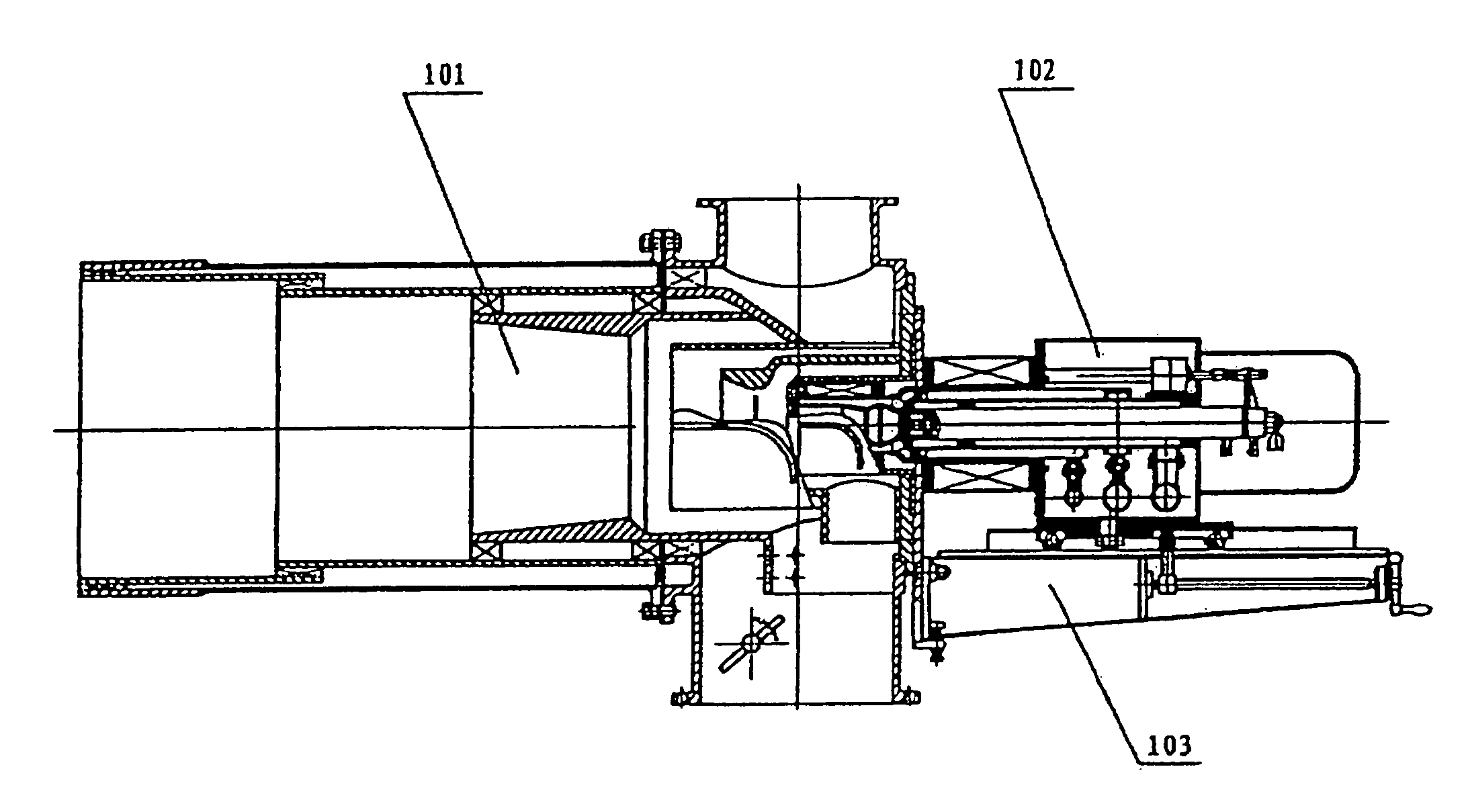
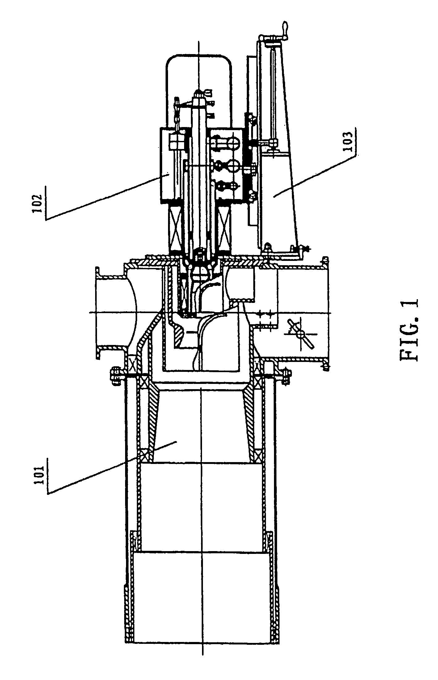
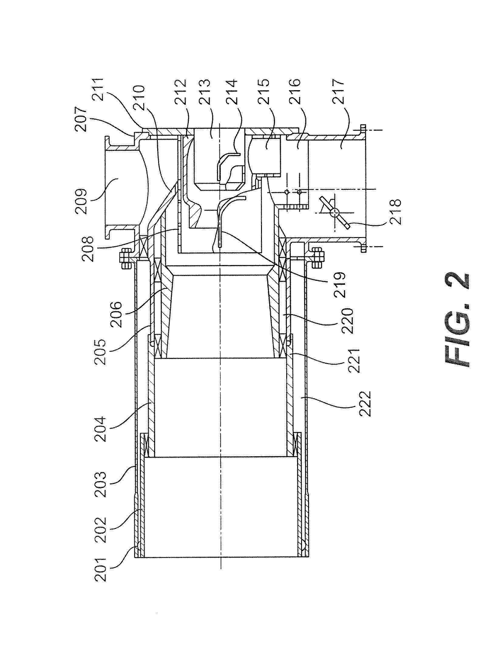
[0023]Now the preferred embodiment of the present invention will be described in details with reference to the accompanying drawings.

[0024]First all the reference signs in the figures will be described in the following table.

[0025]101pulverized coal burner102plasma generator103bracket201burner nozzle202fourth stage burning chamber203burner external cylinder204third stage burning chamber205auxiliary air inner cylinder206second stage burning chamber207powder-air tubes208external cylinder of the first stageburning chamber209auxiliary air inlet tube210primary air guide plate211the flange of the first stage burningchamber212first stage burning chamber213high-temperature plasma transportingpipe214guide plate of the first stage burningchamber215inlet tube of the first stage burningchamber216inlet tube of the second stage burningchamber217primary air-pulverized coal tube218adjustable guide plate for adjusting thepowder concentration219guide plate for the second stage burningchamber220powder...


PUM

PropertyMeasurementUnit
Electrical conductivityaaaaaaaaaa
Concentrationaaaaaaaaaa
Electrical conductoraaaaaaaaaa

Abstract

This invention relates to a plasma igniter for directly igniting the pulverized coal burner. Said plasma igniter consists of a plasma generator which includes a composite anode, an combined type cathode, an electromagnetic coil and a transmitting coil; a pulverized coal burner which comprises multi-stage chambers for conveying igniting coal, an equipment for adjusting concentration of coal powder and a four-stage burner canister; and a generator brace. Said combined type cathode consists of a cathode plate, a fixation nut, a conductive pipe, an inflowing pipe, an inflowing guiding pipe, a cathode lid and a sealing spacer. The lining for generating electric arc is assembled with the front of cathode. An alloy plate is used as the cathode plate. The nozzle that used for cooling the cathode is first convergent and then expansive, and is placed in the middle of the conductive pipe. The plasma igniter has the advantage of stable burning. It can be used as not only a main burner for the boiler but also an igniting burner. Since oil is not used, lots of petroleum source is saved.

Description

TECHNICAL FIELD[0001]The present invention relates to a cathode of a plasma ignition device for directly igniting a pulverized coal boiler, and a plasma ignition device using such a cathode and for directly starting a pulverized coal boiler. The plasma ignition device is used in the starting ignition stage and the low-load stable combustion stage of the pulverized coal boiler, and may serve as the primary burner of the pulverized coal boiler as well.BACKGROUND ART[0002]The starting ignition and low-load stable combustion of the conventional industrial pulverized coal boiler rely on burning oil. In the year of 1999, the pulverized coal boilers of the state power system of China consumed about 2.87 million tons of oil, amounting to about 10 billion RMB yuan in value. Since the 1980's, the technologists of different countries focused on developing technologies adopting plasma technology in directly igniting the pulverized coal. An Australian has developed a plasma ignition device, in w...

Claims


Application Information

Patent Timeline
IPC IPC(8): F23D1/00F23Q5/00F23Q13/00H05H1/24H05H1/30H05H1/34H05H1/42H05H1/48
CPCF23D1/00F23Q13/00H05H1/30H05H1/42H05H1/48H05H1/34F23D2207/00H05H2001/3484H05H2001/3436H05H1/3436H05H1/3484
Inventor WANG, AISHENGTANG, HONGJI, SHUXINWANG, YUPENGTIAN, DONGWANG, GONGLINREN, WEIWUCHEN, XUEYUANSHAO, RUIHUZHANG, XIAOYONGMA, SHUANG
Owner YANTAI LONGYUAN POWER TECH
Why Eureka
Try Eureka