Quantum noise random number generator

a random number generator and quantum noise technology, applied in the field of random number generation, can solve the problems of generating random numbers randomly encoding photons, current optical quantum random number generators are by no means the best possible, and the latter is expensive and relatively slow (100 khz)

Active Publication Date: 2007-10-16
MAGIQ TECH INC
View PDF15 Cites 86 Cited by
  • Summary
  • Abstract
  • Description
  • Claims
  • Application Information

AI Technical Summary

Problems solved by technology

As a consequence, an eavesdropper (“Eve”) that attempts to intercept or otherwise measure the quantum signal will introduce errors into the transmitted signals, thereby revealing her presence.
One of the major problems in quantum cryptography is the generation of random numbers to randomly encode the photons.
From this point of view, current optical quantum random number generators are by no means the best possible.
However, the latter tend to be expensive

Method used


Image

  • Quantum noise random number generator
  • Quantum noise random number generator
  • Quantum noise random number generator

Examples


first example embodiment

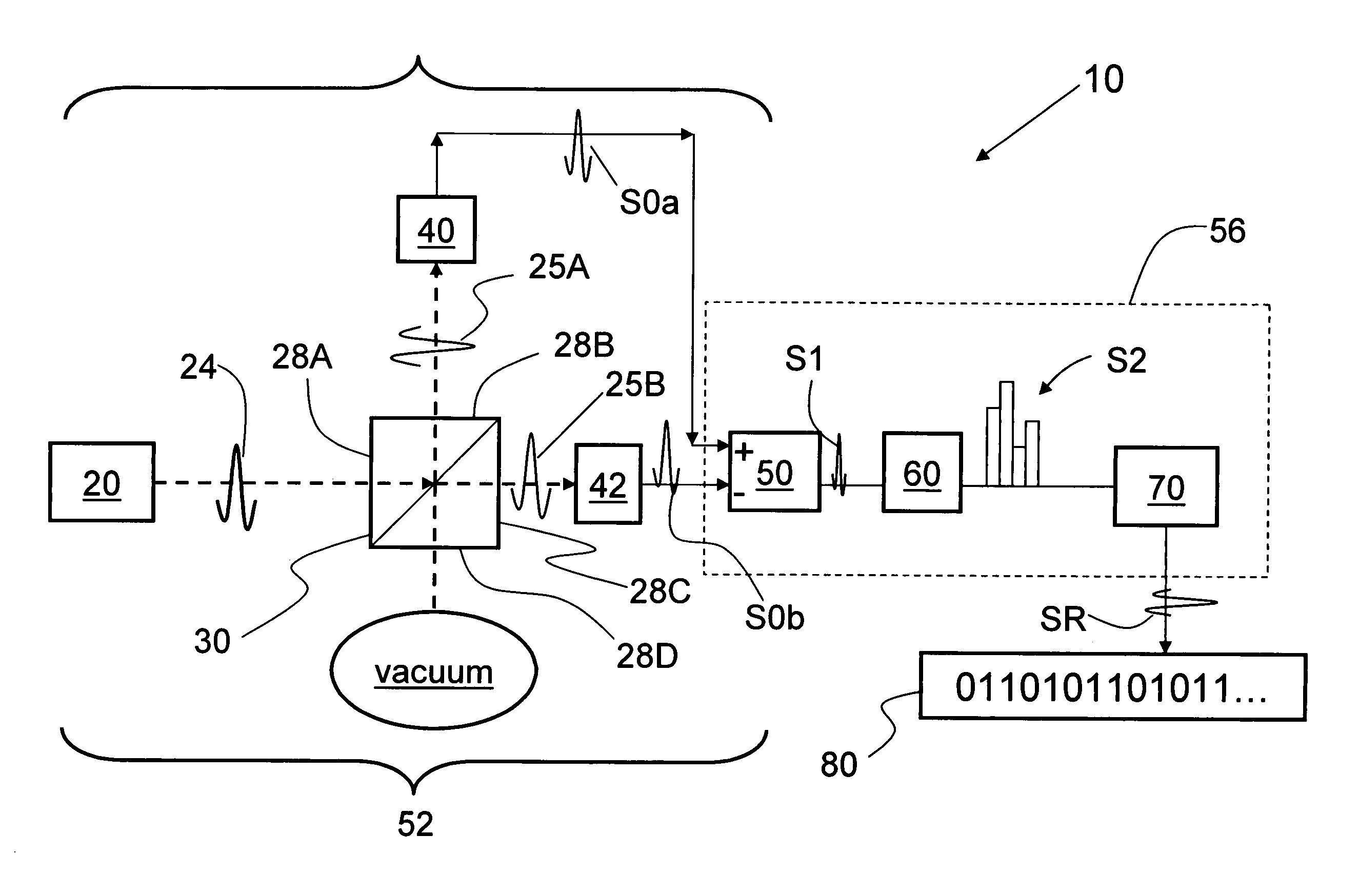
[0021]FIG. 1 is a schematic diagram of a first example embodiment a quantum-noise TRNG system 10 according to the present invention. System 10 includes a laser source 20 adapted to emit a light signal 24, which may be a continuous beam or pulses of light. System 10 also includes a 50 / 50 beamsplitter 30 that has four ports 28A, 28B, 28C and 28D. Beamsplitter 30 is arranged to receive light signal 24 at port 28A. System 10 also includes two photodetectors (e.g., photodiodes) 40 and 42 respectively arranged so as to be in optical communication with corresponding ports 28B and 28C. Port 28D is “open” or “dark,” meaning that the port is subject to vacuum fluctuations. Port 28D is thus shown as connected to a vacuum.

[0022]Photodetectors 40 and 42 are electrically connected to a differential transimpedance amplifier (TIA) 50. The laser source 20, beamsplitter 30, detectors 40 and 42 and the differential TIA 50 constitute a homodyne quantum noise source 52.

[0023]In the example embodiment il...

second example embodiment

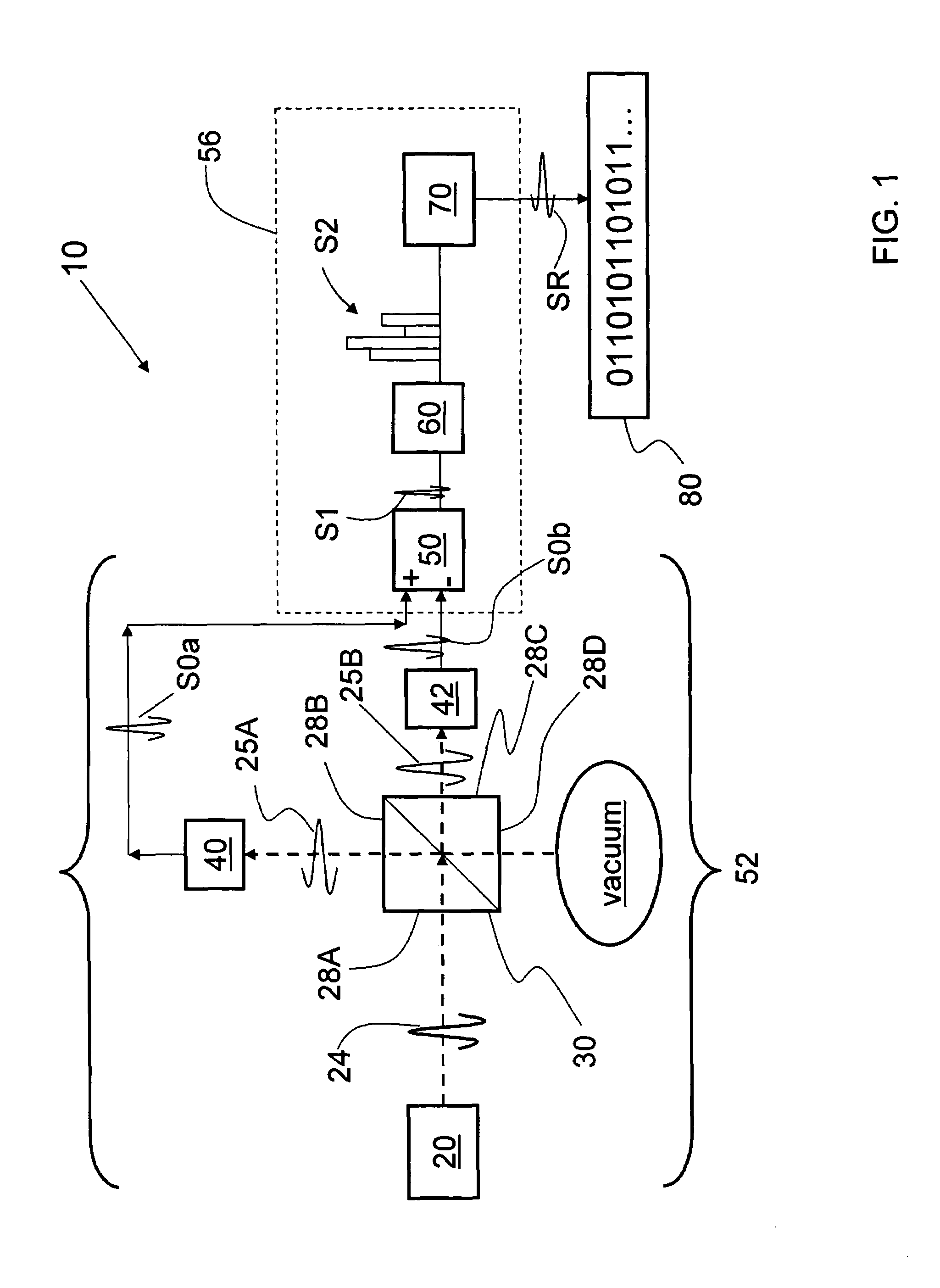
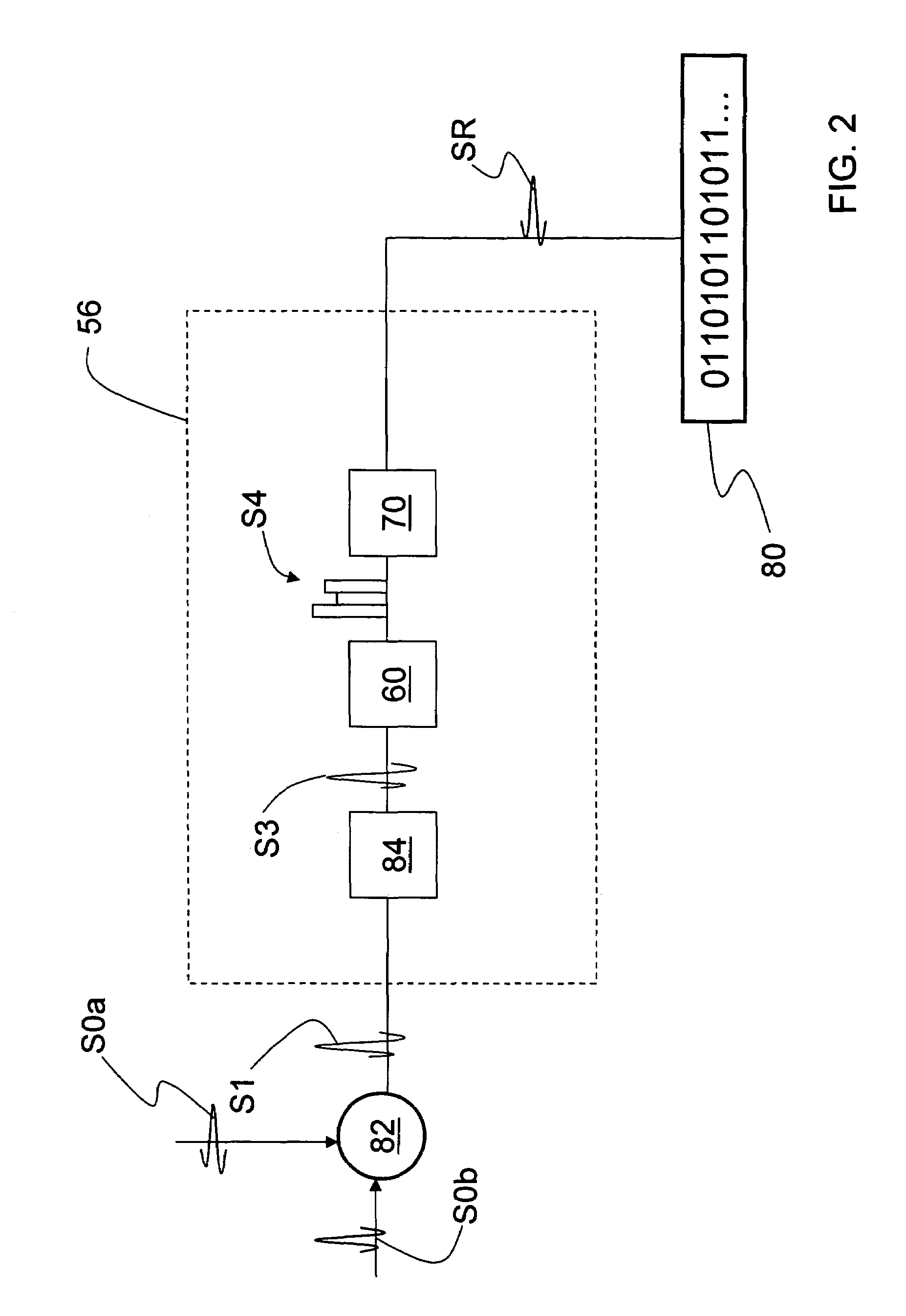
[0033]FIG. 2 is a close-up schematic diagram of the processing electronics 56 associated with a second example embodiment of system 10. In this second embodiment, photodetectors 40 and 42 (FIG. 1) are electrically connected to a subtractor 82. As the term is used herein, “subtractor” means any device that can receive two signals and subtract one from the other to create a difference signal. The laser source 20, beamsplitter 30, detectors 40 and 42 and subtractor 82 constitute homodyne quantum noise source 52.

[0034]Subtractor 82 is electrically connected to processing electronics 56, which includes electrically coupled to one another in sequence a TIA 84, an ADC 60 and transformation electronics 70. Thus, subtractor 82 and TIA 84 function much in the same manner as the single differential TIA 50, though the single differential TIA embodiment typically provides for better bandwidth and better immunity to external noise.

[0035]In the operation of the second embodiment of system 10, subt...

third example embodiment

[0036]FIG. 3 is a close-up schematic diagram of the processing electronics 56 associated with a second example embodiment of system 10. Processing electronics 56 includes a TIA 84 and an ADC 60 between detector 40 and subtractor 82, and a TIA 84 and ADC 60 between detector 42 and subtractor 82. This third embodiment operates in a manner similar to that of the system of FIG. 2, except that the placement of TIAs 84 and ADCs 60 result in the creation of respective analog voltage signals S3a and S3b (“analog photovoltages”) from TIAs 84 and respective digital voltage signals S5a and S5b (“digital photovoltages”) from ADTs 60. Signals S5a and S5b are then digitally subtracted at subtractor 82. This produces a digital voltage difference signal S6, which is received and processed by transformation electronics 70 to create random number signal SR corresponding to random number sequence 80.

QKD System

[0037]FIG. 4 is a schematic diagram of an example embodiment of a folded QKD system 200 that ...


PUM


Abstract

A quantum noise random number generator system that employs quantum noise from an optical homodyne detection apparatus is disclosed. The system utilizes the quantum noise generated by splitting a laser light signal using a beamsplitter having four ports, one of which receives one of which is receives the laser light signal, one of which is connected to vacuum, and two of which are optically coupled to photodetectors. Processing electronics process the difference signal derived from subtracting the two photodetector signals to create a random number sequence. Because the difference signal associated with the two photodetectors is truly random, the system is a true random number generator.

Description

CLAIM OF PRIORITY[0001]This patent application claims priority from U.S. Provisional Patent Application No. 60 / 445,805, filed on Feb. 7, 2003.FIELD OF THE INVENTION[0002]The present invention relates to random number generation, and in particular relates to systems and methods for generating true random numbers.BACKGROUND OF THE INVENTION[0003]Quantum key distribution involves establishing a key between a sender (“Alice”) and a receiver (“Bob”) by using weak (e.g., 0.1 photon on average) optical signals transmitted over a “quantum channel.” The security of the key distribution is based on the quantum mechanical principle that any measurement of a quantum system in unknown state will modify its state. As a consequence, an eavesdropper (“Eve”) that attempts to intercept or otherwise measure the quantum signal will introduce errors into the transmitted signals, thereby revealing her presence.[0004]The general principles of quantum cryptography were first set forth by Bennett and Brassa...

Claims


Application Information

Patent Timeline
IPC IPC(8): G06J1/00
CPCB82Y10/00G06F7/588H04L9/0852H04L9/0662G06N99/002H04L2209/08G06N10/00
Inventor TRIFONOV, ALEXEIVIG, HARRY
Owner MAGIQ TECH INC
Why Eureka
Try Eureka