
Conductive paste and ceramic electronic component

a technology of electronic components and conductive pastes, which is applied in the direction of non-metal conductors, conductors, fixed capacitor details, etc., can solve the problems of reducing the adhesion between the ceramic element and the external conductor, deteriorating the platability of the external conductor, and inferior solder wettability and heat resistance, so as to prevent delamination between the effect of high adhesion of the conductor and the coated member

Active Publication Date: 2007-10-23
MURATA MFG CO LTD
View PDF8 Cites 12 Cited by
  • Summary
  • Abstract
  • Description
  • Claims
  • Application Information

AI Technical Summary

Benefits of technology

The conductive paste forms dense, high-density external conductors with enhanced solder wettability and heat resistance, minimizing plating solution penetration and preventing 'explosions' during component-mounting, ensuring secure joining and delamination prevention.

Problems solved by technology

Therefore, there is a problem in that the molten glass extends to the surfaces of the external conductors to cover the electrode surfaces and this causes a deterioration in the platability of the external conductors.
A deterioration in platability leads to inferior solder wettability and soldering heat resistance.
Therefore, there is also a problem in that a plating solution penetrates the external conductors during plating and this causes a decrease in the adhesion between the ceramic element and the external conductors.
Furthermore, there is a problem in that when the plating solution is present in the external conductors, water contained in the plating solution is vaporized and expanded by heat applied thereto during component-mounting so rapidly as to appear to cause an “explosion” in the external conductors, disturbing their integrity.

Method used


Image

  • Conductive paste and ceramic electronic component
  • Conductive paste and ceramic electronic component

Examples


experiment 1

[0055]In order to obtain a composition shown in Table 1, the following compounds for preparing glass were weighed: B2O3, SiO2, and M2O (K2O, Li2O or Na2O). These compounds were fed in a platinum crucible and then heated at a temperature of 1,000° C. to 1,600° C. for 60 minutes, whereby the compounds were melted into a glass. The molten glass was poured into pure water from the crucible. The resulting glass was wet-ground with a ball mill and then dried, whereby glass powder with an average particle size of 0.5 to 2.0 μm was prepared. According to this procedure, several types of glass powder used in Examples 1 to 8 and Comparative Examples 1 to 4 were prepared.

[0056]These types of glass powder were measured for their softening point with a differential thermal analysis system. An X-ray diffraction analysis showed that these types of glass powder were amorphous.

[0057]Table 1 shows the composition and softening point of the types of glass powder used in the examples and the comparativ...

experiment 2

[0074]Several types of Ag powder used as conductive powder were prepared so as to have an average particle size, an aspect ratio, and a mixing ratio shown in Table 3. The mixing ratio is defined as the ratio of the amount of spherical particles to that of flat particles on a weight basis and may be referred to as a spherical particle-to-flat particle ratio.

[0075]The following materials were mixed: 71% of each type of Ag powder, 5.0% of a type of glass powder, and 24.0% of an organic vehicle on a weight basis. The type of glass powder was the same as that used in Example 2 shown in Table 2, and the organic vehicle was the same as that used in Experiment 1. The mixture was kneaded with a three-roll mill, whereby a conductive paste for forming an external electrode was prepared.

[0076]Several conductive pastes were prepared by this procedure and monolithic ceramic capacitors were prepared by the same procedure as that described in Experiment 1 using the conductive pastes. The monolithic...


PUM

PropertyMeasurementUnit
particle sizeaaaaaaaaaa

Abstract

A conductive paste contains conductive powder, glass powder and an organic vehicle. The glass powder contains about 10% to 31% of B2O3, about 65% to 86% of SiO2, and more than about 0.5% to less than about 5% of M2O on a weight basis, wherein M represents an alkali metal element. A ceramic electronic component includes a ceramic element and an external conductor placed on the component element. The external conductor contains a glass component containing about 10% to 31% of B2O3, about 65% to 86% of SiO2, and more than about 0.5% to less than about 5% of M2O on a weight basis, wherein M represents an alkali metal element.

Description

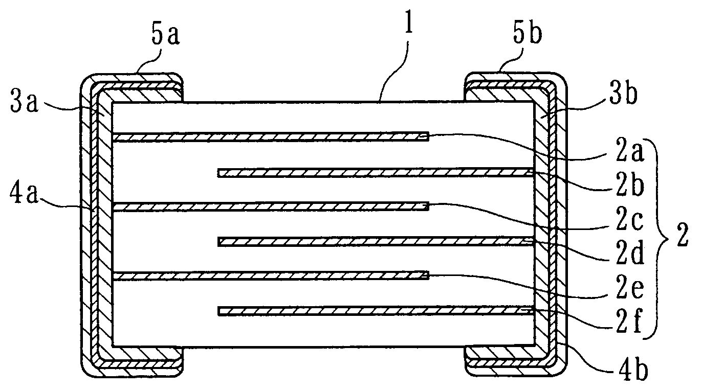
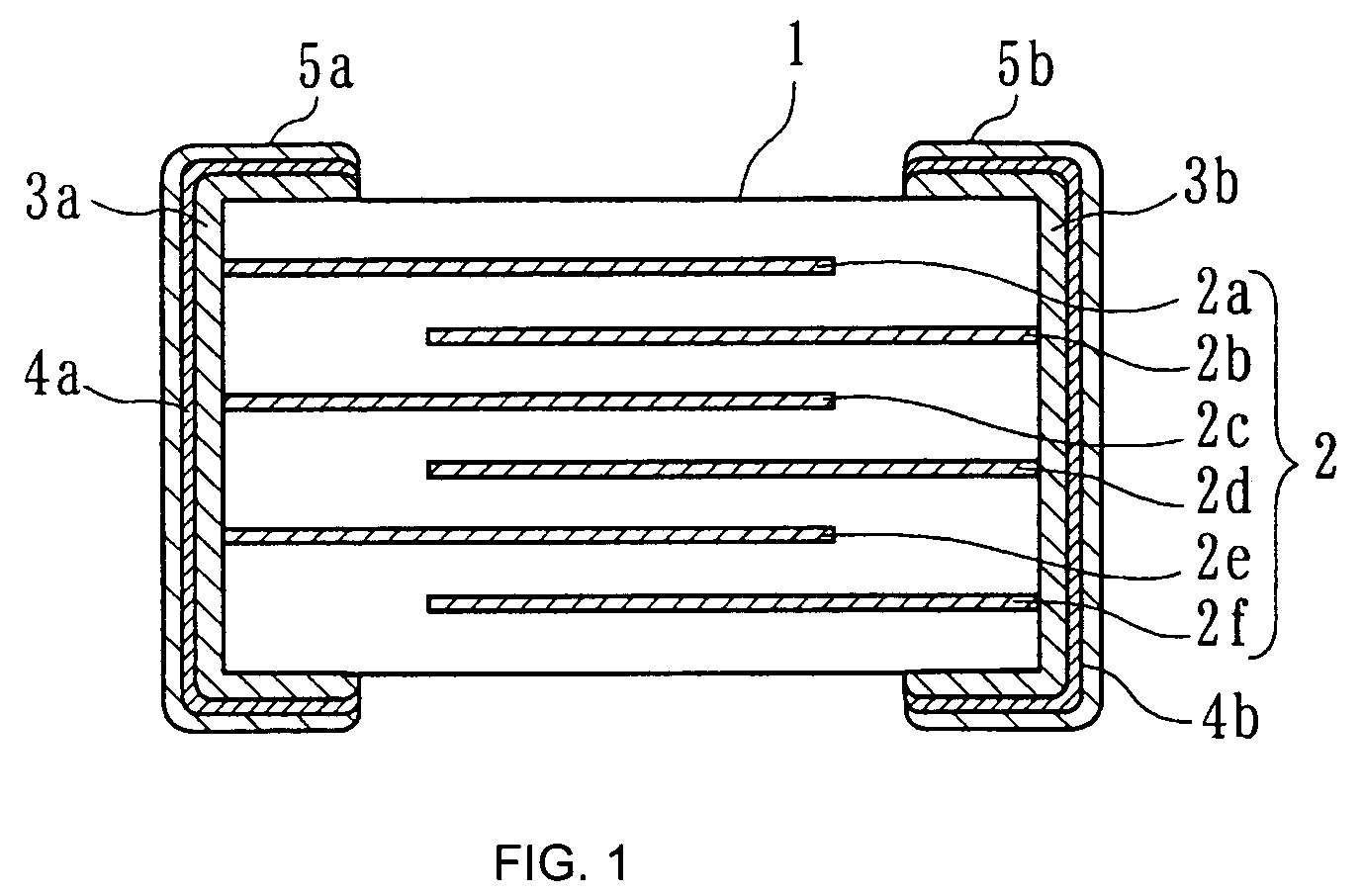
BACKGROUND OF THE INVENTION[0001]1. Field of the Invention[0002]The present invention relates to conductive pastes and ceramic electronic components. The present invention particularly relates to a conductive paste used to manufacture external conductors of ceramic electronic components and also relates to a ceramic electronic component such as a monolithic ceramic capacitor.[0003]2. Description of the Related Art[0004]In general, ceramic electronic components such as monolithic ceramic capacitors are prepared by a procedure in which a conductive paste for forming external conductors is applied onto both ends of ceramic elements and the resulting ceramic elements are dried and then fired. In order to enhance the solder wettability and the soldering heat resistance, the external conductors are coated with metal coatings such as Ni coatings, Sn coatings or solder coatings.[0005]Examples of the conductive paste include a dispersion containing an organic vehicle; conductive powder, such...

Claims


Application Information

Patent Timeline
Patent Type & Authority Patents(United States)
IPC IPC(8): H01B1/22H01C7/00H01B1/02H01B1/16H01G4/232H01G4/30H01G4/33H05K1/09
CPCH01G4/2325H01B1/16
Inventor MIKI, TAKESHI
Owner MURATA MFG CO LTD
Learn More