Capacitive multidrop bus compensation

a multi-drop bus and compensation technology, applied in the field of data integrity improvement, can solve the problems of phase and amplitude aberration in unwanted signal reflection into the bus, and attenuation of amplitudes at frequencies where the phase error is significant, so as to improve signal integrity, increase the amount of desirable harmonic content, and alter the frequency response of the bus

Inactive Publication Date: 2007-10-23
ROUND ROCK RES LLC
View PDF10 Cites 8 Cited by
  • Summary
  • Abstract
  • Description
  • Claims
  • Application Information

AI Technical Summary

Benefits of technology

[0013]The present invention improves the signal integrity of a high speed fully loaded multidrop memory bus without compromising the signal integrity when the bus is lightly loaded. A typical high speed multidrop memory bus is designed for impedance matching between the bus and the various memory modules that can be inserted into the memory slots. However, minor impedance mismatches introduce unwanted signal reflections into the bus. The presence of the reflections cause phase and amplitude aberrations in the frequency response of the bus. The frequencies in which these aberrations occur are related to the electrical length of the bus, and the location of poles and zeros in the frequency domain (caused by the parasitic capacitance and inductance). In the prior art bus structure, these aberrations occur relatively low in frequency when compared to the operation frequency of the bus. In the present invention, a compensating element, such as a capacitor that connects the bus to a reference plane, is placed approximately midway, i.e., approximately 40% and 60% of the distance between the memory controller and the memory slots. The compensating element alters the frequency response of the bus by introducing another pole into the frequency domain. By carefully choosing and placing the compensating element, the frequency response of the bus can be altered to peak at a lower frequency, thereby increasing the amount of desirable harmonic content. While this technique also increases the degree of phase error at high frequency, the introduction of the additional pole in the frequency domain serves to attenuate the amplitude of high frequency signals, thereby mitigating their affect on the frequency response. Therefore, adding the compensating element results in an equalization of signal amplitudes at frequencies where the phase error is minimal, and an attenuation of amplitudes at frequencies where the phase error is significant. This results in a bus structure which exhibits better rise times, which permits the bus to be operated at a higher data rate.

Problems solved by technology

However, minor impedance mismatches introduce unwanted signal reflections into the bus.
The presence of the reflections cause phase and amplitude aberrations in the frequency response of the bus.
Therefore, adding the compensating element results in an equalization of signal amplitudes at frequencies where the phase error is minimal, and an attenuation of amplitudes at frequencies where the phase error is significant.

Method used


Image

  • Capacitive multidrop bus compensation
  • Capacitive multidrop bus compensation
  • Capacitive multidrop bus compensation

Examples


Embodiment Construction

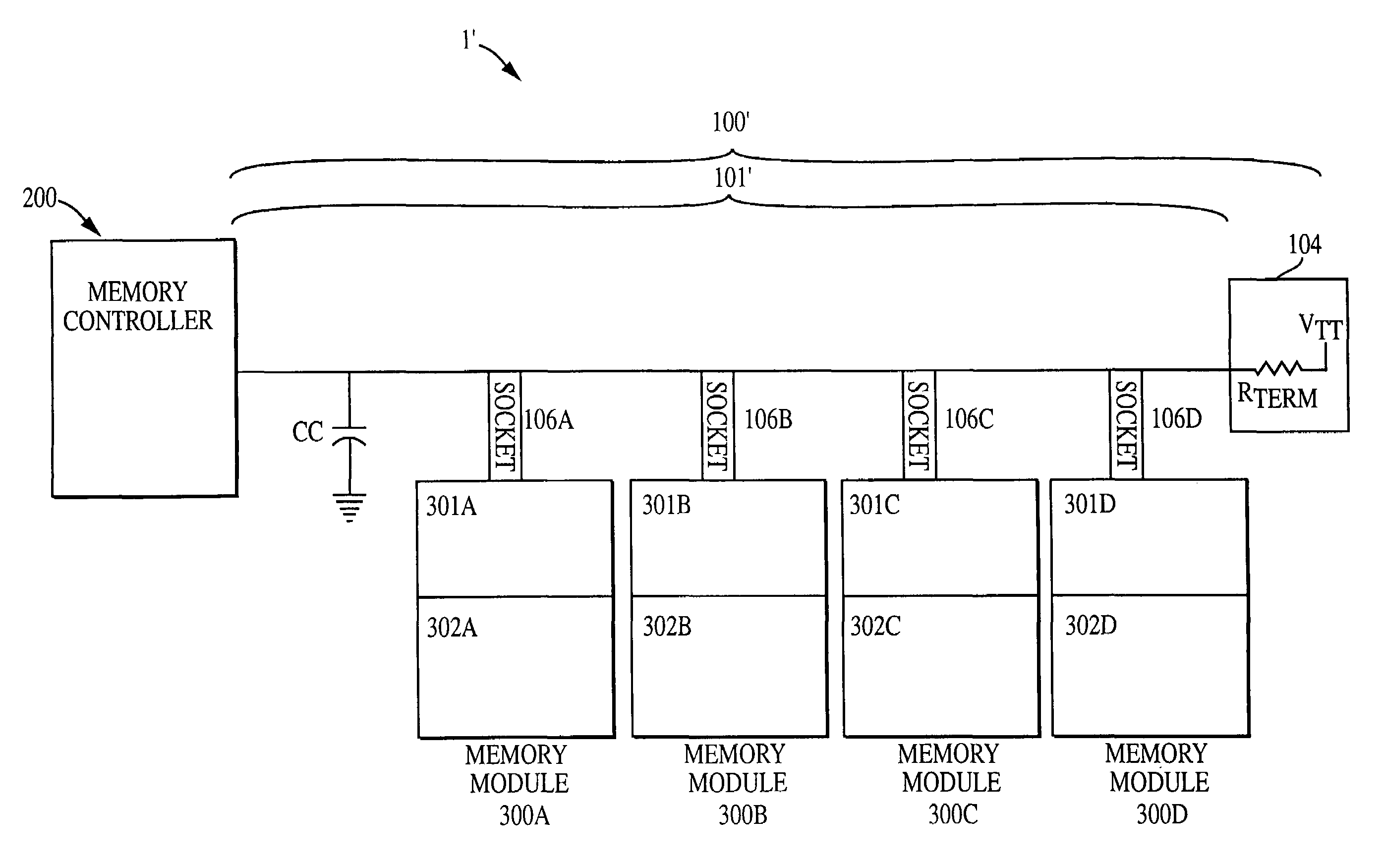
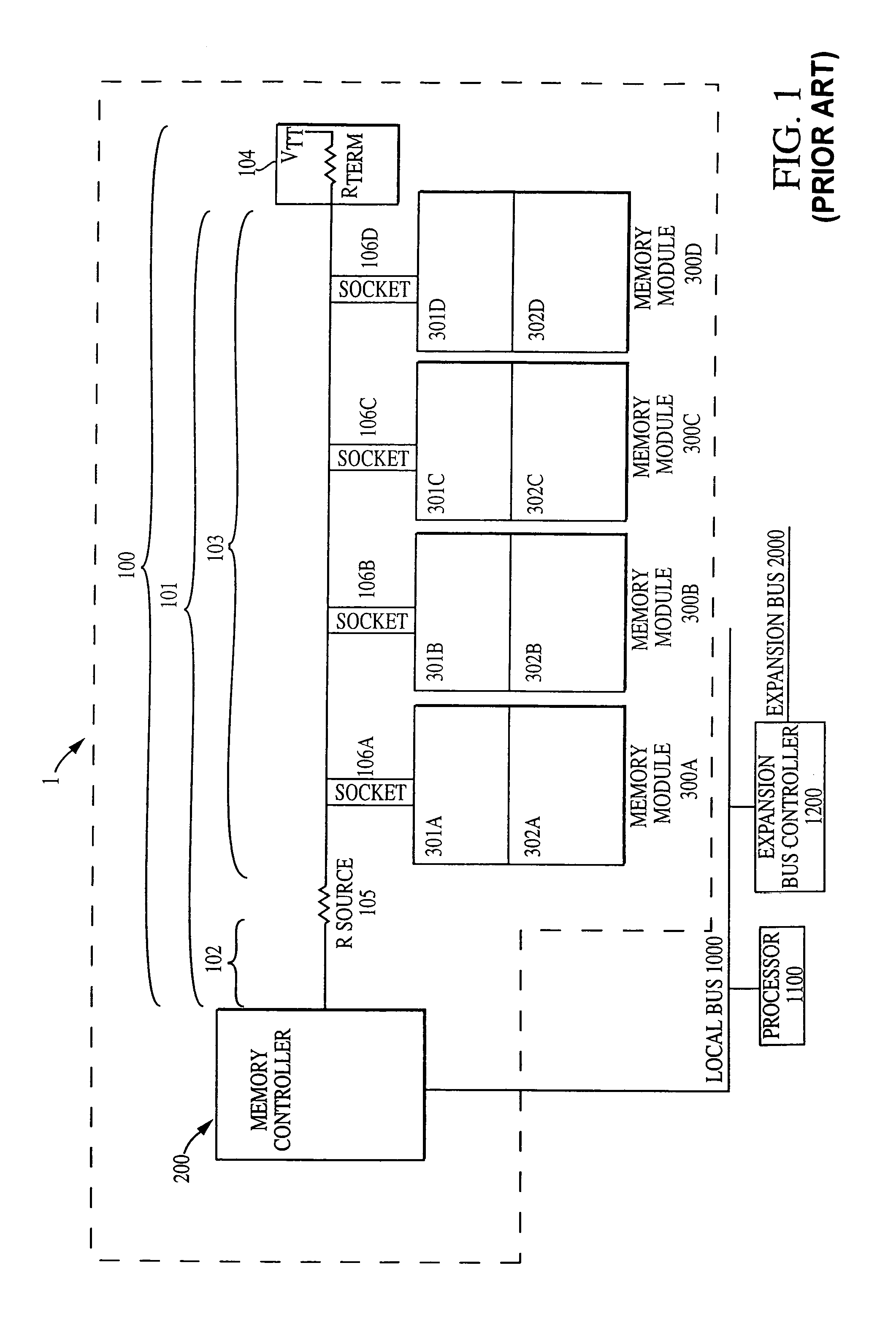
[0022]Now referring to FIG. 4, a first exemplary embodiment of the present invention is illustrated. FIG. 4 shows a memory system 1′ including a memory controller 200, a memory bus 100′ including a transmission line 101′ to which a plurality of sockets 106a-106d are attached. A plurality of memory modules 300a-300d may be inserted into the plurality of sockets 106a-106d. As in the conventional bus 100 (FIG. 1), the memory bus 100′ is terminated by a terminator 104, which includes a termination resistor Rterm and a termination voltage source VTT. In this exemplary embodiment, the termination resistor Rterm is a 27 ohm resistor, however, different resistances may be used. For example, a larger resistance, such as 37 ohms may also be used to reduce current requirements. Two significant differences between the exemplary bus 100′ and the prior art bus are the removal of the source resistor 105 of the prior art bus and the insertion of a compensating element, such as a compensating capaci...


PUM


Abstract

The signal integrity of a high speed heavily loaded multidrop memory bus is often degraded due the numerous impedance mismatches. The impedance mismatches causes the bus to exhibit a nonlinear frequency response, which diminishes signal integrity and limits the bandwidth of the bus. A compensating element, such as a capacitor which ties the bus to a reference plane (e.g., a ground potential), or an inductor wired in series with the bus, is located approximately midway between the memory controller and the memory slots. The use of the compensating element equalizes signal amplitudes and minimizes phase errors of signals in an interested frequency range and diminishes the amplitudes of high frequency signals which exhibit high degrees of phase error. The resulting bus structure has increased desirable harmonic content with low phase error, thereby permitting the bus to exhibit better rise time performance and permitting a higher data transfer rate.

Description

[0001]This application is a divisional of U.S. application Ser. No. 09 / 637,796 filed Aug. 11, 2000, now U.S. Pat. No. 6,745,268, the entire disclosure which is hereby incorporated by reference.FIELD OF THE INVENTION[0002]The present invention relates to improving signal integrity of data signals applied to a bus and, more particularly, to the use of a compensating element for improving the signal integrity of a fully loaded high speed memory bus.BACKGROUND OF THE INVENTION[0003]Memory systems for computers provide many memory devices on a common bus to allow larger storage and transmission capacities than can be obtained with a single memory device. The memory devices are multiplexed on to a multidrop bus to reduce the pin count of a memory bus master or controller. Most of these systems require user upgradeable or replaceable components to allow future expansion or repair of the memory subsystems. Typically, these systems are upgraded on a module basis, where the memory module (e.g...

Claims


Application Information

Patent Timeline
Patent Type & Authority Patents(United States)
IPC IPC(8): G06F13/00H01P5/08H01P5/12H03B1/00H03H7/38G06F13/40
CPCG06F13/4086
Inventor GREEFF, ROYLEE, TERRY R.
Owner ROUND ROCK RES LLC
Why Eureka
Try Eureka