

Road surface waste water treatment device and tubular water treatment unit
- Summary
- Abstract
- Description
- Claims
- Application Information
AI Technical Summary
Benefits of technology
Problems solved by technology
Method used
Image

Examples
embodiment 1
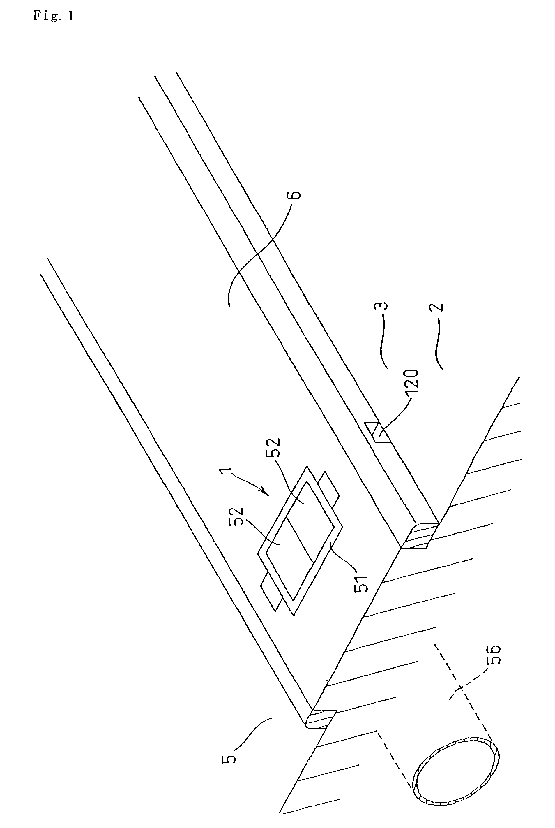
[0058]As illustrated in FIG. 1, the water treatment apparatus 1 of the invention is installed underneath the ground at a distance of 20 m in an area 6 between the road-side 3 of the road 2 and a sidewalk 5, where plants are planted. The top of the apparatus 1 is adjusted to ground level and the apparatus is covered by a cover plate 52 placed in a support frame 51. Road surface water runs into the apparatus 1 through a curb inlet 120, is purified while passing through the apparatus and exits from an outlet to the sewage pipe 56.
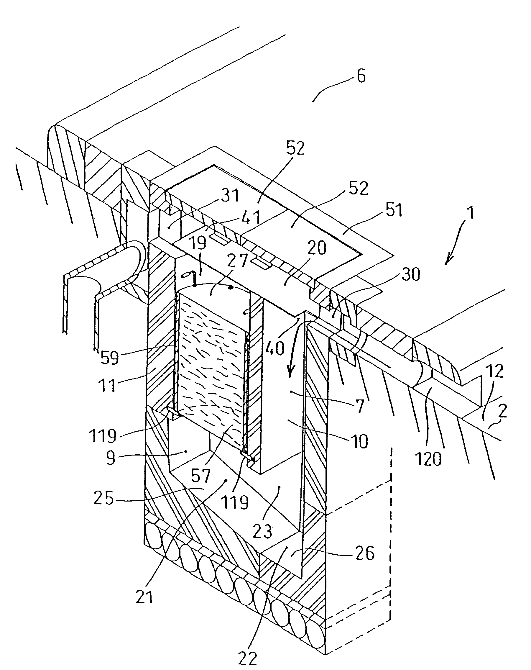
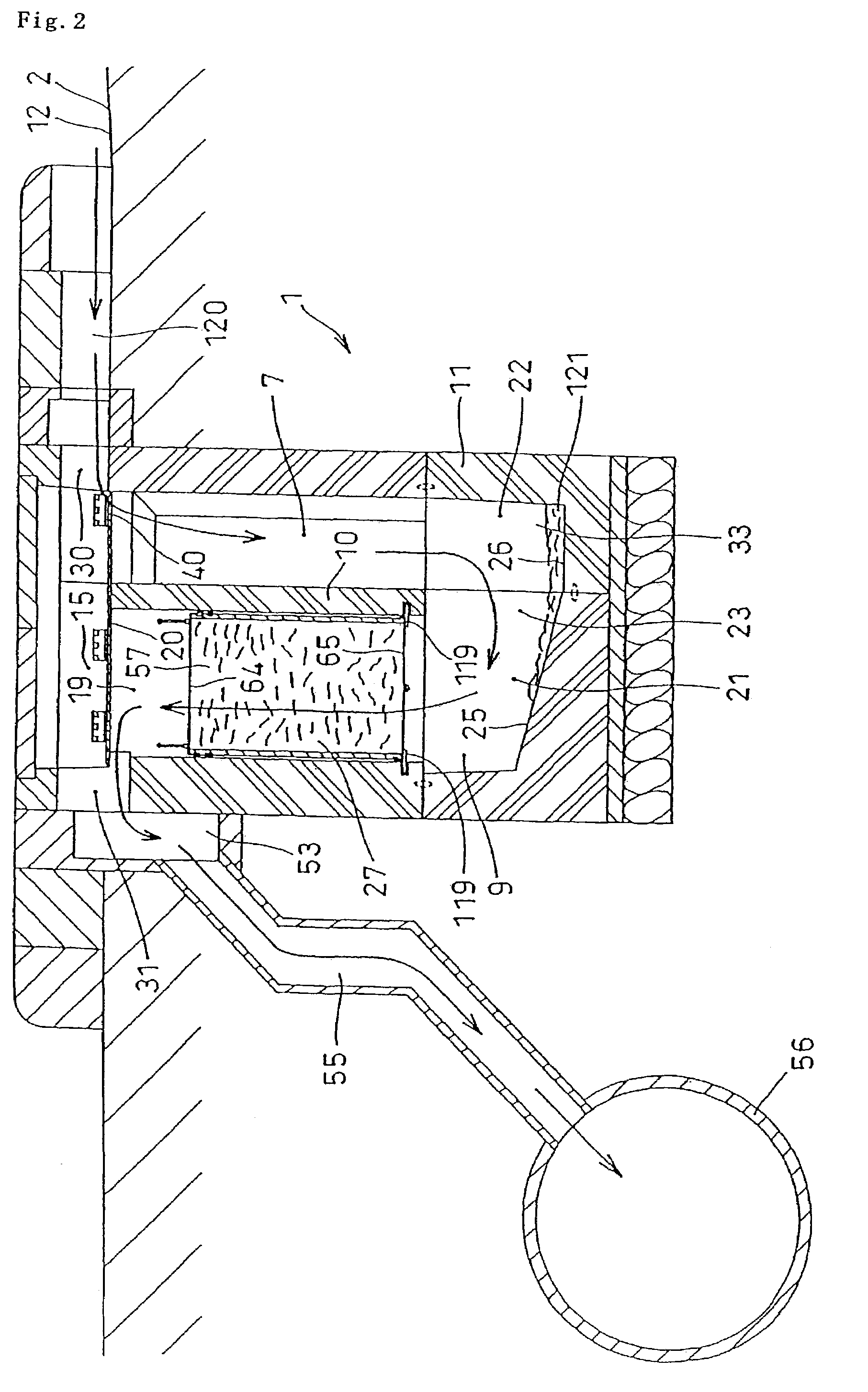
[0059]As illustrated in FIG. 2, the water purification apparatus 1 of the invention comprises a concrete block 11, the inside of which is separated by a wall 10 and also has formed therein a maintenance tank 7 and a treatment tank 9, both of which are connected at their lower ends, thereby, the drain water from the road surfaces flows into the maintenance tank 7 indicated by arrows in FIG. 2, then flows downward in the maintenance tank 7, flows upward passing ...
embodiment 2
[0092]FIG. 26 and FIG. 28 show another embodiment of the invention of the water purification apparatus. It is basically the same as Embodiment 1. The water purification apparatus comprises a concrete block box 11, the inside of which is separated by a wall 10 and forms a maintenance tank 7 and treatment tank 9, both of which are connected to each other at their lower ends. Thereby, the drain water from the road surfaces flows into the maintenance tank 7 indicated by the arrows. The water flows downward in the treatment tank 9, then upward in the maintenance tank 7. The pollutants are removed by the water purification materials 57 in the treatment tank 9 and the purified water is discharged to a sewage pipe 56.
[0093]The bottom 25 of the treatment tank 9 is inclined toward the maintenance tank 7 and the treatment container 59 is detachably placed therein and both tanks are connected at their lower ends. A cover plate 20 is placed to cover the openings 19, 17 of both tanks. The differe...
embodiment 3
[0095]FIG. 29 and FIG. 30 show another embodiment of the container 27 of the treatment materials. It is basically the same as Embodiment 1 and in a preferred embodiment, the cross-section of the container 59 is rectangular and both ends are covered by covers 125, 126, which comprise mesh cloth 123 and are secured to the container with bolts. The treatment tank 9 is preferably rectangular and extends vertically and there is provided support members 129 made of angle members at the inside lower end thereof and sealing members 131 are glued on the top of the support members 129.
[0096]The container 27 is placed inside the treatment tank 9 and the lower end is supported on the support members 129. The sealing members 131 are compressed by the weight of the container 59 so the gap G between the container 59 and the inside wall 132 of the treatment tank 9 is sealed. The runoff water flows into the container 59 through the inlet 30 and flows upward or downward and the water is purified whil...
PUM
| Property | Measurement | Unit |
|---|---|---|
| Height | aaaaa | aaaaa |
Abstract
Description
Claims
Application Information