System for a virtual dew point sensor

a technology of virtual dew point and sensor system, applied in the direction of braking system, electric control, instruments, etc., can solve the problems of premature engine system component failure, unfavorable engine system performance, and engine system component cycle life, and achieve the effect of reducing the amount of exhaust gas

Inactive Publication Date: 2007-11-06
CATERPILLAR INC
View PDF14 Cites 19 Cited by
  • Summary
  • Abstract
  • Description
  • Claims
  • Application Information

AI Technical Summary

Benefits of technology

[0008]In yet another aspect, the present disclosure is directed to a method for controlling exhaust gas recirculation with respect to an engine. The method includes determining if a first temperature indicative of a temperature of an inlet gas directed toward an inlet manifold is less than or equal to a first dew point. The first temperature is indicative of a temperature at a first location with respect to the inlet manifold. The method also includes determining if a second temperature indicative of a temperature of an inlet gas directed toward an inlet manifold is less than or equal to a second dew point. The second temperature is indicative of a temperature at a second location with respect to the inlet manifold and the second location is different that the first location. The method further includes reducing an amount of exhaust gas recirculated from downstream of an engine toward a mixer if either of the first or second temperatures is less than or equal to the first and second dew points, respectively.

Problems solved by technology

As such, the existence of condensation within the engine system may reduce engine system component cycle life, cause premature engine system component failure, and / or undesirably affect engine system performance.
Additionally, the apparatus associated with the method of the '848 patent may require a humidity sensor exposed to the combustion air which may potentially decrease the integrity of the inlet manifold or of another component of the exhaust gas recirculation system.
Furthermore, the method of the '848 patent only determines the likelihood of condensation within the inlet manifold which may not sufficiently monitor condensation with respect to additional engine system components.

Method used


Image

  • System for a virtual dew point sensor
  • System for a virtual dew point sensor
  • System for a virtual dew point sensor

Examples


Embodiment Construction

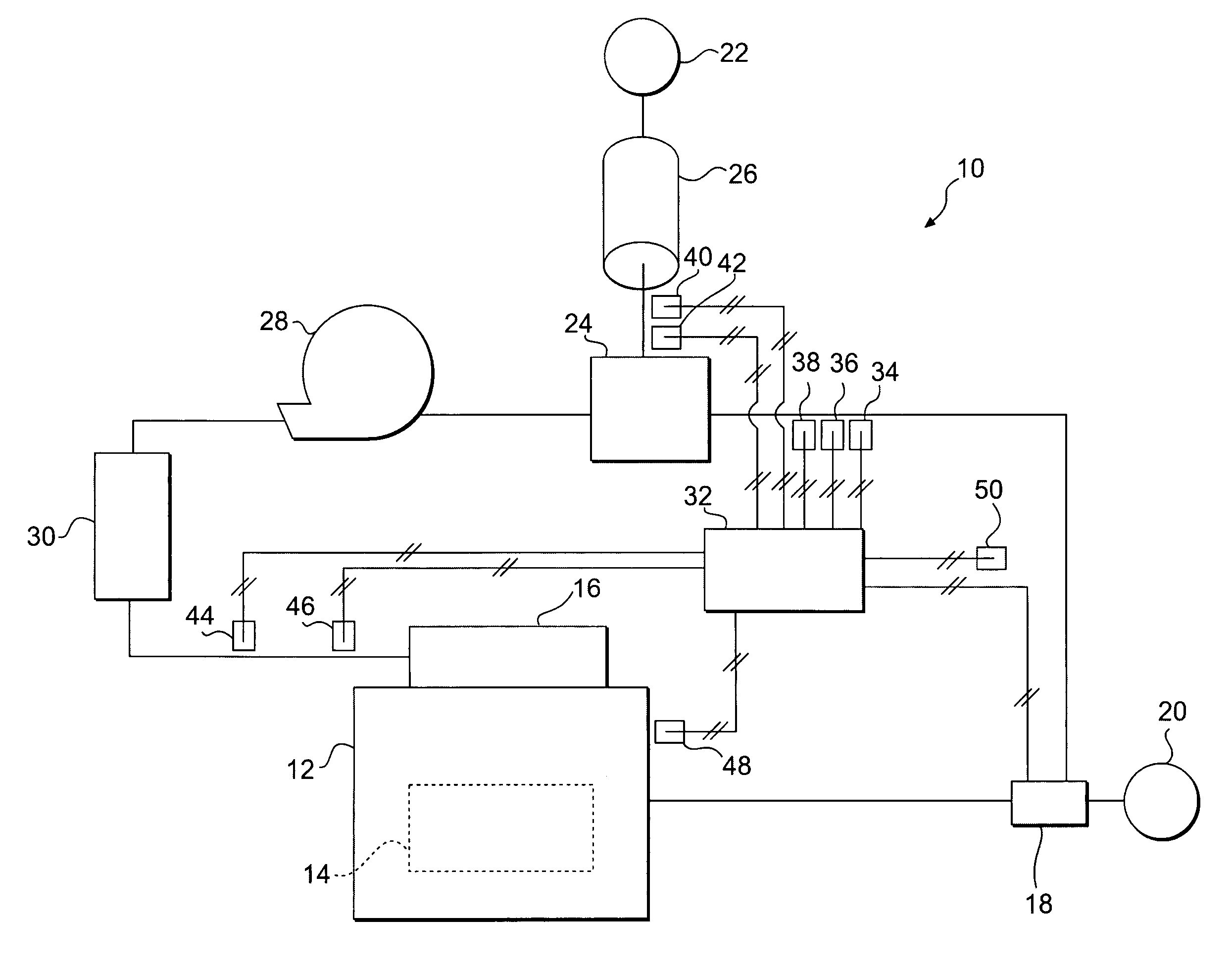
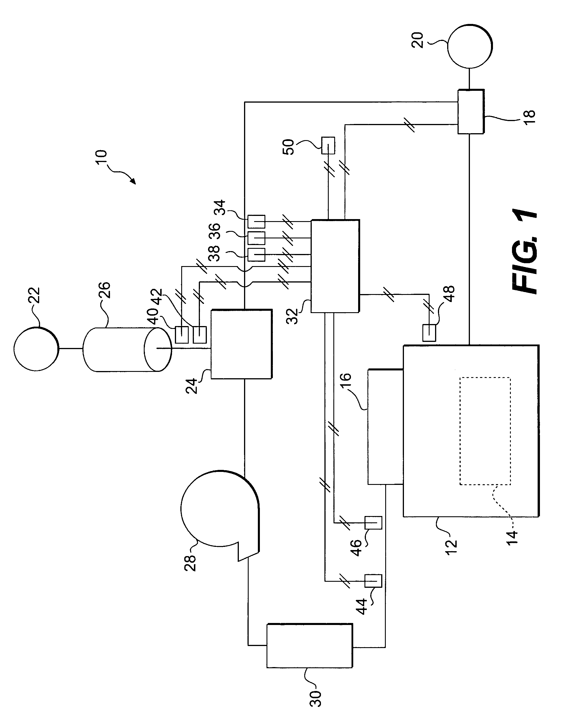
[0013]FIG. 1 illustrates an exemplary first engine system 10. First engine system 10 may include an engine 12 having a combustion chamber 14 and an inlet manifold 16. Engine 12 may be configured to transform potential chemical energy, e.g., fuel, into mechanical energy, e.g., torque, via a combustion process, e.g., a two or four cycle piston cylinder combustion arrangement. Exhaust gas may be directed from combustion chamber 14 toward an environment 20 for release thereto. A portion of the exhaust gas may selectively be directed to a mixer 24 via a valve 18. Valve 18 may include a solenoid actuated variable output valve configured to divert a portion of the exhaust gas produced within combustion chamber 14 toward mixer 24. First engine system 10 may also include an air filter 26 configured to filter air received from an environment 22 and direct the filtered air toward mixer 24. Environments 20 and 22 may be the same or different environments and may, for example, include ambient ai...


PUM


Abstract

A system for a virtual dew point sensor is disclosed including a method for operating the virtual dew point sensor. The method includes determining a first humidity ratio indicative of the humidity associated with an ambient air as a function of at least a relative humidity associated with the ambient air. The method also includes determining a second humidity ratio indicative of the humidity associated with an exhaust gas as a function of at least one engine parameter. The method also includes determining a third humidity ratio indicative of combustion air directed toward an inlet manifold of an engine as a function of the first and second humidity ratios. The method further includes determining at least one dew point indicative of the combustion air as a function of the third humidity ratio and a pressure indicative of the combustion air.

Description

TECHNICAL FIELD[0001]The present disclosure relates to a system for a virtual dew point sensor system and, more particularly, to a method and apparatus for a virtual dew point sensor.BACKGROUND[0002]Turbocharged and / or supercharged engine systems typically include a compressor and an air cooler upstream of one or more combustion chambers of an engine. Often, the combustion air comprises a mixture of ambient air and recirculated exhaust gas in an attempt to reduce undesirable emissions produced during combustion. Recirculated exhaust gas often includes considerable amounts of water vapor and, in relatively cold environments, the temperature of the combustion air may be lowered below the dew point of the combustion air resulting in condensation developing within one or more locations of the engine system, e.g., within components and / or conduits. Condensation may combine with acidic substances within the recirculated exhaust gas, e.g., sulfuric or nitric substances, to form aqueous aci...

Claims


Application Information

Patent Timeline
Patent Type & Authority Patents(United States)
IPC IPC(8): B60T7/12F02B47/08G01M99/00
CPCF02D41/005F02M25/0755G01N25/66F02B29/0406F02D2200/0402Y02T10/47F02M25/0727F02D2200/0418F02M26/46F02M26/23Y02T10/40
Inventor DURAND, JAMES C.
Owner CATERPILLAR INC
Why Eureka
Try Eureka